
PART FIVE
NAVIGATION SSYTEMS
| LORAN (STANDARD) |
| I. |
Principles of Operation |
129 |
| |
|
A. General Description of Loran |
129 |
| |
|
B. Advantages of the Loran System |
130 |
| |
|
C. Limitations of Loran |
132 |
| |
|
D. The Loran Equipment |
132 |
| II. |
Other Loran Systems |
133 |
| III. |
Loran Charts and Basic Information |
134 |
| AN/APN-4 (AIR-BORNE LORAN) |
| I. |
Function |
137 |
| |
|
A. Primary Purpose |
137 |
| |
|
B. Secondary Uses |
137 |
| II. |
Description |
137 |
| |
|
A. Main Components |
137 |
| |
|
B. Scope Presentation |
137 |
| III. |
Tactical Employment |
140 |
| |
|
A. Operational Search and Patrol Missions |
140 |
| |
|
B. Loran Signal Coverage |
141 |
| |
|
C. Navigational Uses |
141 |
| |
|
D. Tactical Uses |
141 |
--127--
[BLANK PAGE]
--128--
PART FIVE
NAVIGATION SYSTEMS
LORAN (STANDARD)
I. PRINCIPLES OF OPERATION
A. A GENERAL DESCRIPTION OF LORAN. The accuracy, range and speed of use of loran surpass that of most other navigational aids. The basic principle is simple. Pairs of radio stations transmit signals on the same radio frequency. Transmissions of signals is not continuous, but intermittent, each station sending out at regular intervals a short signal, or pulse, followed by a comparatively long interval of silence. These pulses are radiated in all directions from the transmitting stations and travel at a constant speed, 161,800 nautical miles per second (approximate). The pulses from a given pair of stations are synchronized so that there is a definite time difference in their arrival at any geographical point. This time difference of arrival is measured in microseconds (millionths of a second) and is constant for all points on the earth's surface whose difference of distance from the two stations is the same. The focus of all points having a given time difference is a hyperbolic curve known as a loran line of position. See figure 5-1. Special loran charts have been printed which show these lines of position for all station pairs now in operation.
With the loran equipment the navigator measures the time difference in the arrival of a pair of pulses at his position. From a loran chart he determines directly his line of position
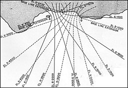
Figure 5-1.--Families of hyperbolas from the loran stations.
"P" is a double-pulsed master station common to both pairs. "Q" and "R" are slave stations.
--129--
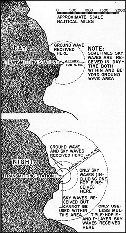
Figure 5-2.--Daytime and nighttime zones
of signal reception from a single loran station.
on the earth's surface, without calculation. The intersection of two such lines determines a loran fix.
13. ADVANTAGES OR THE LORAN SYSTEM. 1. Range.--The effective range of loran varies between 500 and 1,400 miles. Two types of loran signals are received, ground waves and sky waves. The maximum effective range of ground waves over sea water is about 500 to 700 nautical miles in the daytime, and about 350 to 500 miles at night. Usually, sky waves are present only at night, but they are received at much greater distances so that the maximum effective range of loran at night is extended to between 1,200 and 1,400 nautical miles. See figures 5-2, 5-3, and 5-4.
Many factors affect the useful range of radio waves, such as weather conditions, time of day or night, time of year, frequency of transmission, power output of transmitting stations and the nature of the earth's surface (land or water). Most of these factors are beyond the scope of this discussion. With the power and frequencies now used, standard loran is primarily an over-water system of navigation, and the range values given are average values for transmission and reception over sea water. Over land the effective range is reduced, varying between 70 and 150 nautical miles for ground waves and between 1,000 and 1,300 nautical miles for sky waves.
2. Accuracy.--Defining the accuracy of loran in a generalized statement is somewhat difficult as too many factors are involved. The accuracy with which a loran line of position can be obtained depends primarily upon the type of signals (ground or sky waves) and the location of the aircraft relative to the two transmitting stations. Other factors are weather conditions, accuracy of station synchronization, accuracy of the charts, and skill of the operator.
3. Times required to obtain a fix.--Under favorable conditions, a skilled operator can obtain a reading (time-difference measurement) for a line of position in less than a minute. Readings for two or three lines of position may be taken and the position of the (ix plotted within 3 to 5 minutes. Under the most unfavorable conditions, obtaining a single time-difference reading may require 3 or 4 minutes. Once the time-difference readings have been obtained, plotting the lines of position is a simple process which the average operator will accomplish easily in 2 or 3 minutes. In comparison with celestial navigation, the average time required for a loran three-line fix is 3 to 5 minutes, as against the average time of a three-line celestial fix of 20 to 25 minutes. The speed with which an accurate fix may be obtained is one of the most valuable characteristics of loran in aircraft.
4. Homing.--Homing is possible with loran, as in other forms of radio navigation. Loran, however, offers one important additional
--130--

Figure 5-3.--Depending upon the time of day or night, loran signals may follow a ground path (ground waves), they may be reflected from ionosphere layers (sky waves), or there may be a combination of received signals consisting of ground and sky waves.
feature: it is possible to home to any geographical point within range of the transmit t ing stations. The advantages of this characteristic are obvious when compared to the RDF or radio compass with which homing is restricted to a course toward the transmitting station.
5. Effect of adverse weather conditions.--The reliability of loran readings is only slightly affected by adverse weather conditions. Severe magnetic disturbances may prevent the use of weak signals, but normal electrical disturbances merely increase the difficulty of obtaining a good reading. The accuracy of the reading may be affected to some extent, but the reading can nearly always be used if consideration is given to its probable error. The weather at the point of reception is of little consequence, and readings may be obtained almost as easily in rough air as in smooth.
6. Radio silence.--Radio silence may be maintained at all times because no signals are transmitted from the aircraft. The aircraft merely receives the radio signals broadcast by the transmitting station, hence it does not expose its posit ion to the enemy. This is an important factor in wartime.
7. Effect of directional distortion negligible.-- Loran measures the time difference of arrival of radio waves rather than direction of arrival. Direct ional distortion may be disregarded as no bearings are taken or received in order to determine the position of the aircraft. The difference in arrival time of loran signals due to directional distortion is negligible first, because the angular distortion increases the time of travel by a very small amount, and, second, because both signals are usually subject to the same increments.
8. Accuracy not dependent upon the aircraft's compass or chronometer.--Loran lines of position are fixed with respect to the earth's surface. Thus they are independent of compass error and correct observatory time-two factors critical in radio and celestial navigation

Figure 5-4.--From left to right, above, is shown the order in which the various kinds of loran signals
will appear on the scope.
--131--
respectively. A system which is independent of these two factors possesses obvious inherent advantages.
9. Restricted use.--Part of the time difference in the reception of the two signals is a coding delay whose purpose is to restrict the use of loran to friendly aircraft. Loran charts and tables have been computed for a fixed value of this coding delay; but, if necessary, it is possible to change the delay and issue to all navigators a correction value to be applied to all readings before plotting lines of position. Up to the present date there has been no change in the coding delay and no coding correction values have been issued.
10. Secrecy and isolation of transmitting stations.--Transmitters cannot be used by the enemy as beacons to direct their aircraft to vital areas because stations are located in isolated positions. Furthermore, enemy detection of the location of individual transmitting stations is difficult because all stations in an area operate on one radio frequency.
11. World-wide coverage.--Although some of the advantages of loran are of great value in wartime, its fundamental advantages are primarily navigational. These will continue to be of great importance in peacetime.
12. Simple antenna system.--Loran operates with simple straight-wire antennas, either fixed or trailing, which eliminates complications of rotating loops and other directional types of antenna arrangements.
C. LIMITATIONS OF LORAN. Navigators must remember that loran is only a new method of determining a line of position. It is not a substitute for navigation, but rather an excellent navigational aid. Intelligent use of loran requires an understanding of its limitations as well as its advantages.
Loran is a complex piece of electronic equipment containing 43 vacuum tubes. It requires attention and care, and is of necessity relatively fragile. In flight, voltage regulation and temperature changes are uncertain, which may change the alignment. Also, constant vibration over a period of time may change any of the screw driver adjustments. However, under normal conditions, only slight adjustments will be necessary and these can be made in a very few minutes.
D. THE LORAN EQUIPMENT. 1. Transmitting stations.--Loran transmitting stations for long-range, over-water navigation are usually located at prominent points along a coast line or on small islands. The distance between them normally ranges from 200 to 600 nautical miles, with approximately 400 miles considered the optimum from the standpoint of coverage and accuracy. If the geographical situation is unfavorable, the separation may be as small as 100 miles or as great as 600 miles.
Each pair of stations whose signals are synchronized has its own set of fixed lines of position. They are so located that two or more pairs of stations cover strategic areas, with the lines of position intersecting at favorable angles for obtaining accurate loran fixes.
In order to economize on station installations, one station may be made common to two pairs. In this case it sends out two entirely distinct sets of signals, each set being synchronized with the signals from an adjacent station. From an operating standpoint, however, a common station may be regarded as two separate stations at one location. A number of pairs covering the same general geographical area may operate on the same radio frequency and const itute what is called a "chain," even though some of the station pairs are independently located. In any chain operating on the same radio frequency, identification of a given pair is accomplished by control of the pulse frequency at which the two stations transmit their signals.
2. Equipment carried in the aircraft.--Airborne loran equipment consists of a loran radio receiver, an electronic time-measuring unit known as the loran indicator, special loran charts, and loran tables.
The loran radio receiver is a superheterodyne receiver in which loran signals are detected, amplified, and then passed to the loran indicator. The receiver and power supply form an integral unit containing a total of 16 radio tubes mounted in one cabinet.
The loran indicator is an electronic "stop watch" which measures, in millionths of a second, the time difference in the arrival of a pair of pulses. It is a unit containing a
--132--
cathode-ray tube and 26 vacuum tubes, mounted in the second cabinet of the installation.
The two units are connected by means of special cables. With the connecting cables, the total weight varies from 73 to 85 pounds.
Loran charts are an essential part of the system when loran equipment is used in aircraft. They enable the operator to translate the time differences directly into lines of position. The lines of position for each pair of stations are printed in separate colors and are clearly marked for easy identification. Loran charts are equal in importance to the equipment itself.
Loran tables containing data for plotting loran lines of position are used when loran charts are not available. Tables are preferred by some navigators on surface vessels, who prefer to utilize their usual plot sheet and put the loran fixes thereon.
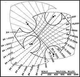
Figure 5-5.--Typical layout of an SS loran system. Stations "A" and "B" form one pair, stations "C" and "D," the other. The area enclosed by the solid line constitutes the service area.
II. OTHER LORAN SYSTEMS*
A. INTRODUCTION. In addition to the standard loran system, which is intended primarily for over-water navigation, there are three variations of it which have assumed prominence. They are: the SS loran system, the AT loran system, and the mobile loran system. The SS ami AT systems were developed particularly for navigation use over inland areas.
B. THE SS LORAN SYSTEM. The sky wave synchronized loran system (SS loran) was developed primarily to provide accurate loran coverage oxer large land areas, but it may be used equally well over water when it is desired to sec ure a high degree of accuracy over a large area. The principal disadvantages of the SS loran system are that it operates only at night when sky waves are consistently available, and will not work on nights when propagation conditions are so erratic as to make synchronization impossible.
In the SS loran system, the two stations in each pair are separated by a distance of approximately 1,000 statute miles. This is far too great a distance to permit synchronization by means of the ground wave, even over sea water. Instead, the stations are synchronized by the first-hop-E sky wave. Since the sky wave is propagated almost as well over land as over water, the use of the sky wave for synchronization permits the system to be set up over inland areas.
A typical layout of stations for the SS loran sytem is shown in AAFfigure 5-5. The small circles around each station bound areas within which it is inadvisable to use the sky wave because of proximity to the stations. The useful service area of the system is shown within the solid line. It will be noted that the SS loran system permits the stations to be placed on opposite sides of the service area. This straddling of the objective places the region of greatest accuracy directly over the objective, and, in addition, introduces favorable crossing angles. The net result is that fixes accurate to about 2 miles or less are available throughout the service area, with the best accuracy located directly in the center of the service area.
SS loran has proved to be one of the most important adaptations of the standard loran system. Stations set up many miles away from enemy positions provide lines of position covering enemy territory. In some cases occupation of certain positions by the enemy makes it difficult to place the SS loran transmitters in ideal locations. Complete coverage of enemy-held
*Excerpts from BuShips Loran Manual No. 278.
--133--
territory may be impossible. Nevertheless, lines of position from a single pair may be invaluable. Accurate approach to enemy targets can be made by using the homing procedure previously explained.
In order to obtain fixes, single SS lines of position may be combined with lines of position obtained by some other means. An important tactical use combines loran and radar search or bombing equipment. A loran line of position passing through a prospective radar target is selected for homing and the radar screen is observed until the target comes into view. This procedure is particularly useful in approaching islands, coast lines, and cities.
C. AT LORAN. The air-transportable loran system (AT loran) differs from standard loran only in the form of equipment used in the ground stations, and in that shorter base lines are used. The AT loran ground station electronic equipment is of lower power and is considerably lighter in weight and smaller in size than the standard loran ground station equipment. Sine standard loran ground station equipment. Since speed is the essence of AT loran operations, there is usually no time for the preparation of charts by the advanced methods used by the Hydrographic Office. Nor is there time for the transportation of such charts from the United States to the operating theater. Attached to each AT loran system is a group of trained computers and draftsmen, and reproduction equipment to prepare charts in the field. The speed with which such charts can be computed and drawn is greatly enhanced by the use of a polyconic or Lambert projection. The charts supplied for AT loran operations are of this variety. They are based on the existing aeronautical charts of the region, in the scale of 1:2,000,000 (about 32 statute miles to the inch).
In all other respects, so far as operation of the aircraft equipment is concerned, the service supplied by AT loran equipment is the same as that supplied by the standard loran equipment. The ground-wave accurate service range of the AT loran transmitters is several hundred miles less than that of standard loran, due to the short base lines and the lower power output. The sky-wave accurate service range is about the same as the ground-wave range. The signals will be usable with very low accuracy to distances of 1,000 to 1,400 miles.
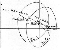
Figure 5-6.--On loran service charts the solid lines showing ground or sky-wave coverage are labeled to indicate the frequency channel, the basic recurrence rate, and the station pair number.
D. MOBILE LORAN. Mobile stations are ones using a standard station apparatus housed in automobile trucks, equipped with surveying and chart providing facilities, and organized with especially trained personnel equipped to go into a remote location, have stations on the air, charts provided and giving service in one month. They are therefore suited to providing quick, temporary service. They are equivalent to standard stations in all respects apparent to the user of the service.
III. LORAN CHARTS AND BASIC INFORMATION
A. LORAN FREQUENCY CHANNELS. Four operating frequencies have been assigned for loran transmission. These channels, designated for reference as 1, 2, 3, and 4, are as follows:
1-1,950 kc.
2-1,850 kc.
3-1,900 kc.
4-1,750 kc.
There may be as many as eight pairs of transmitting stations employing any one frequency channel. Each of the pairs, however, will pulse at a different rate, enabling the equipment at the receiving location to be synchronized to receive and match only the selected pair.
--134--
B. PULSE RECURRENCE RATES. Two basic pulse recurrence rates are used, designated as follows:
Any eight-station chain may employ a given basic pulse recurrence rate, each one of the eight pairs differing slightly in recurrence rate from 25 to 257/16 pulses per second for the low rate and 331/3 to 341/9 pulses per second for the high rate.
C. LEGENDS. With reference to the loran coverage charts (See fig. 5-6). the legend desig-nal ing the coverage provided by any designated station pair may he as follows:
2L 1
where "2" denotes the second frequency channel, 1,850 kilocycles; "L" denotes low basic recurrence rate, 25 per second; "1" denotes station pair recurrence rate.
On the loran charts, each of the station pair hyperbolas is similarly designated and in addition bears the time line designation, thus:
2L 1-4,500
D. CHARTS. Loran charts are published by the Hydrographic Office or the Aeronautical Charts Service, USAAF, for use aboard ships and aircraft. Ground-wave lines of position from the various station pairs are printed in distinguishing colors and are further identified by the legends described above. Line of position are shown at the closest interval of time (in microseconds) satisfactory for the scale of the chart. This varies between 100 and 10 microseconds.
In some areas, where five or six rates overlap, only the three or four most useful ones are plotted on the charts.
As basic information the loran charts carry isogonic lines, the location of radio stations, and aircraft facilities. Soundings are not shown.
Charts are available on several scales. The various series designations are:
| Series |
| VL-70 |
|
70 nautical miles per inch at mid. latitude. |
| VRL-200 |
|
About 60 nautical miles per inch. |
| VL-30 |
|
30 nautical miles per inch at mid latitude. |
| VL-15 |
|
15 nautical miles per inch at mid. latitude. |
| N (North Pacific) |
|
15 nautical miles per inch at mid. latitude. |
| NW (North Atlantic) |
|
1° longitude is 4 inches. |
NOTE: For reference purposes, a series of chartlets, showing loran signal coverage for all loran stations now in operation have been included in the appendix, appearing at the end of this book. These chartlets are from the U. S. Navy Hydrographic Office publication 1-L (c), entitled "Loran Charts and Service Areas."
--135--
AN/APN-4
--136--
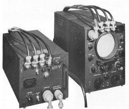
NOTE: There are three models of air-borne loran gear in current use? Excepting for circuit improvements, there are no fundamental differences in the receiver (RA) units. There are, however, marked operational and scope display differences in the indicator (ID) units (ID-6, ID-6A, ID-6B AN/APN-4). The ID-6 indicator, an early model, was used primarily for reception of stations operating on the 25-cycle repetition rate. Also, it presented a "dot" alignment pattern on the scope. The ID-6A retains the "dot" alignment pattern but is provided with a front-panel switch for setting the gear either to the 2r>- or 33%-cycle signal repetition rate. Indicator ID-6B is similar to ID-6A excepting that the alignment pattern is of the characteristic "stairs" type.
AN/APN-4 (AIRBORNE LORAN)
I. FUNCTION
A. PRIMARY PURPOSE. AN/APN-4 air-borne loran is an electronic device specifically designed for the purpose of receiving and measuring the time-difference in the arrival of pulsed signals from specially located shore-based loran transmitters.
Hydrographic Office loran charts, used in conjunction with the time-difference information, allow the navigator to determine the aircraft's line of position, or, with several lines of position, an actual "fix."
B. SECONDARY USES. 1. Depending upon the geographic location of a selected target within the loran signal transmission coverage area, a line of position, or combinations of lines, can be chosen as a course for the aircraft to "home" on the selected target.
2. In conjunction with other navigational information, loran time readings can be employed to determine accurately drift and wind at various altitudes, irrespective of visibility or weather.
II. DESCRIPTION
A. MAIN COMPONENTS. An AN/APN-4 installation consists of:
-
Superheterodyne receiver-power supply unit.
-
Indicator unit.
-
Fixed, or trailing wire antenna.
-
Connector cables.
1. Receiver-power supply unit.--One unit houses both the superheterodyne receiver and the power supply. Primary source for the power supply is taken from a 115-volt, 800-cycle aircraft alternator. The power supply converts this to the various voltages required for operation of the receiver and indicator circuits.
The receiver has four "fixed-tune" channels which must be preset to operate in designated frequency channels, depending upon the global area in which the equipment is to be used.
2. Indicator unit.--The indicator unit con-tains the cathode-ray tube upon whose screen the signals picked up by the receiver are displayed and measured. The indicator unit also contains those electronic circuit features and controls which permit:
The selection of any one of eight pairs of transmitting stations operating within a given frequency band.
The viewing of signal, time-measurement, and calibration screen displays.
Matching of the signals.
Adjustment of signal gain and signal amplitude balance.
Screwdriver calibration adjustments.
B. SCOPE PRESENTATION. By means of a sweep speed control, eight separate scope presentations are displayed successively on the scope screen. See figures 5-7 and 5-8. Sweep speeds 1, 2, 3, and 4 produce patterns which, through adjustment of the operating controls, permit the signals from a selected pair of stations to be matched. Sweep speeds 5, 6, and 7 present scope displays which can be read to indicate, in terms of microseconds, the time difference resulting from matching the signal pips. Sweep speed 8, together with the setting of the
--137--
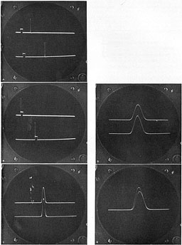
Figure 5-7.--Loran signals from a pair of stations shown on various sweep speeds:
A-Sweep speed one.
B-Sweep speed one.
C-Enlarged signals on pedestal, sweep speed two.
D-Sweep speed three.
E-Signals superimposed, sweep speed four.
--138--
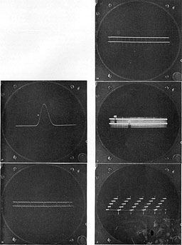
Figure 5-8.--Loran indicator counter and calibration patterns:
F-Perfect loran match, sweep speed four.
G-Sweep speed five.
H-Sweep speed six.
I-Sweep speed seven.
J-Sweep speed eight.
--139--
station selector switch, indicates the alignment, or lack of alignment, of the equipment.
1. Sweep speed 1.--Two horizontal traces are produced on the scope screen, each trace having in it a relatively broad square pulse, or pedestal. The top trace pedestal is stationary; the lower trace pedestal is movable along the trace. Depending upon the setting of the gain control, noise in the form of grass, and signal pips will appear on the traces. Some signal pips will drift across the traces. One pair may appear which is stationary. Use of the Left-Right switch shifts the position of the stationary pips until the top signal is on the top pedestal with the lower signal to the right of the upper one. Manipulation of the coarse and fine delay controls moves the lower pedestal along its trace to a point underneath the lower signal pip.
2. Sweep speed 2.--The pedestal portion of the traces, with signals, is magnified and reproduced over the entire scope screen when the equipment is adjusted to sweep speed 2. Further adjustment of the fine delay control permits the signals to be lined up, one under the other.
3. Sweep speed 3.--A portion of the pedestals with the signals thereon, is reproduced over the entire screen when the equipment is adjusted to sweep speed 3. Further adjustment of the fine delay control permits the signals to be more accurately aligned.
4. Sweep speed 4.--Here the signal and trace display is essentially the same as for sweep speed 3 except that only one trace shows, with one signal superimposed upon the other for further matching. In this position, the amplitude balance and gain controls are employed to match the signals for equal amplitude. This completes the signal-matching procedure.
5. Sweep speed 5.--Sweep speed 5 indicates the time difference in units of 10 microseconds. Values of time-difference less than 10 microseconds must be interpolated.
6. Sweep speed 6.--Sweep speed 6 indicates the time-difference in units of fifty microseconds.
7. Sweep speed 7.--Sweep speed 7 indicates the time-difference in units of five hundred microseconds.
The total time-difference is the sum of the readings for sweep speeds 5, 6, and 7.
| Example: |
Microseconds |
| Sweep speed 5 |
39
|
| Sweep speed 6 |
400
|
| Sweep speed 7 |
2000
|
| Total |
2439 |
This figure represents the hyperbola on the loran chart which must be selected or interpolated, for a given pair of stations, to indicate the aircraft's line of position at the time the match was finally accomplished (sweep speed 4).
A second reading can be taken from a pair of stations whose family of hyperbolas intersect those of the first pair. Advancing or retiring the lines for course made good during the interval of taking readings produces a fix whose accuracy is almost wholly dependent upon the operating skill and ability of the navigator.
III. TACTICAL EMPLOYMENT
A. OPERATIONAL SEARCH AND PATROL MISSIONS. It may be assumed that, as a general rule, pilots and navigators are familiar with loran as a navigational aid. Too often, however, the operations officer is not aware of a loran's capabilities, particularly with reference to its ability to contribute materially, in the planning stage, to the assignment of aircraft for routine operational search and patrol missions in specific areas.
When loran is used to define search and patrol areas, the operations officer is assured that a given search or patrol mission may be executed with a higher degree of accuracy and that the designated area is covered more effectively than would be possible by the employment of other navigational methods.
Specifically, the factors which contribute to the useful tactical employment of loran by the personnel concerned with its operation are:
Exact knowledge of position regardless of weather.
Accurate rendezvous between aircraft and ships.
Less fuel necessary to be carried for navigational error.
Accurate patrol and search cruising.
--140--
B. LORAN SIGNAL COVERAGE. Whether or not loran can be employed depends upon:
1. The geographic location of loran transmitters and their day and night service ranges.
2. The strength of signal reception in a given service area. (This depends upon such factors as an over-water path between transmitter and receiver, signal attenuation due to take-off of signal over intervening land masses, and variation of signal strength with altitude.)
3. Inherent accuracy of loran lines of position for a specific area. (In areas near the baseline extension of a pair of transmitters, accuracy of time-difference readings is low.)
4. The number of pairs of stations servicing si given area and the "cut" of the resultant lines of positions.
C. NAVIGATIONAL USES. Loran provides a fast and accurate method of obtaining time-difference readings which can be converted directly into lines of position on the navigator's chart. Two or more lines of position are used to determine a fix. Single lines of position can be used to obtain:
Fixes (by crossing with celestial LOP's or radio bearings).
Estimated positions.
A constant check on the accuracy of the DR track.
Ground speed.
Drift angle (if compass deviation is known accurately).
Deviation on certain headings (if drift angle can be observed with the drift meter).
Furthermore, loran gives a constant indication of the aircraft's position relative to any given line of position. Courses corresponding to the bearings of the fixed loran lines can be made good with a high degree of accuracy. Winds can be determined between fixes only a few miles apart. Since drift angles can be determined, double drift (or spot) winds can be determined at night. Single lines of position can be combined with drift meter readings in such a way that spot winds may be determined without changing course of the aircraft.
D. TACTICAL USES. Loran can be used tactically in the following ways:
1. Homing.--There is a loran line of position through any geographical point within range of a pair of stations. A track coinciding with a particular line of position may be made good by flying aircraft headings that will maintain the correct time-difference reading. Thus loran lines of position may be used as lines of approach to a target. The method is simple and accurate. The time-difference reading of the line through the target is preset on the indicator and a heading is chosen which will intercept the desired line of position on one side of the target. Definite arrival and time to turn for the final approach is indicated by the observed pulses coming into coincidence. This method automatically provides the necessary correction for drift, hence it is independent of predetermination of wind.
2. Patrol missions.--The homing method of maintaining a track along a loran line of position may be used effectively in patrol missions or in making a systematic search of a given area. The general technique is to follow one line of position for a given distance, then to change course so as to intercept another line of position parallel to the first and separated from it by any desired distance. This back-and-forth traversal of parallel lines of position will insure that the area is completely covered.
If loran lines from another pair of stations are available, determination of wind and also the aircraft's position becomes a simple process. Once the heading to maintain track has been determined and the track plotted on the chart it is only necessary to obtain a cross line of position to get a fix. The short time required to do this makes it possible to give immediate position reports whenever they are needed.
Patrol missions may be divided into a number of specific types, each involving some particular type of flight pattern. Proper use of loran insures precise navigation and a greater effectiveness in accomplishing the purpose of the mission. Some of the various types of missions are listed below, together with some of the specific advantages of loran which are applicable to the type of mission.
--141--
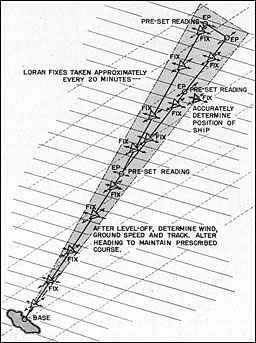
Figure 5-9.--The shaded section above represents the area of a sector search to be searched visually, by radar, or both. By utilizing loran as a planning method before flight and obtaining fixes during flight, the navigator is assured of adequately covering the assigned area. The position of observed shipping can be determined with a high degree of accuracy.
a. Sector search (See fig. 5-9):
Maintains course easily.
Winds quickly determined.
Ability to fly under or in clouds and still obtain an accurate position at any time.
Accurate position reports possible almost immediately upon sighting vessels, other aircraft or submarines.
b. Barrier search (See fig. 5-10):
Maintains course accurately.
When more than one aircraft is flying barrier and visibility is poor, controlled separation between aircraft can be insured.
c. Gambit (See fig. 5-11):
Rapidity of obtaining fixes enables navigator to check position frequently, consequently the possibility of deviating from the gambit aircraft is almost nil.
d. Convoy coverage (See fig. 5-12):
Position may be checked easily and accurately.
Accurate position reports can be reported immediately.
e. Sweeps (See fig. 5-13):
Prescribed "overlap" and courses can be accurately flown.
"Contacts" can be reported accurately.
f. Rescue missions:
Reported position of survivors can be reached directly without necessitating a search or causing doubt as to whether or not the search aircraft is at the reported position.
g. Mine laying (See fig. 5-14):
Accuracy and rapidity with which winds can be determined enable the navigator to compute the ballistic
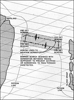
Figure 5-10.--Barrier search in a strait or between two headlands, augmented by the use of loran. Establishment of course lines at a preset turning point assures adequate and complete coverage of the assigned area.
--142--
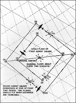
Figure 5-11.--When a detected submarine submerges the effectiveness of a gambit search diminishes if the square is off center; that is, not equidistant from the original point of contact. Loran can be employed to accurately locate the point of submergence in terms of latitude and longitude and to insure that the actual track of the gambit corresponds to the predicted courses of the square.
wind and the approach heading for the mine laying run prior to the time of determining the wind by radar.
3. Bombing mission.--a. Homing method of approach simplifies all navigational problems.
b. After evasive action, position of aircraft relative to desired line of approach can be obtained almost instantly at any altitude and regardless of visibility.
c. Dangerous flak areas can be avoided easily without excessive detours. Approach to, or passage beyond, a restrictive line of position is indicated almost instantly.
d. A low-altitude approach along a line of position toward the target is possible even under conditions of poor visibility.
e. Lines of position intersecting the approach lines give very accurate ground speed checks for determining ETA at target. If intersecting lines of position pass through the target, the method used in approaching a homing line of position gives an accurate ETA at the target.
4. Long range navigation.--a. On long over-water flights, course may be maintained accurately.
b. Immediate indication is given of any changes in wind or drift.
c. Winds can be determined quickly after passing through a front, or after a change of altitude.
d. With adequate coverage, it is always possible to home to any desired geographical point.
e. Flights can be planned and made without large deviations from course due to unexpected changes in winds or weather.
5. Traffic guidance.--Aerial traffic over congested routes can be controlled by assigning
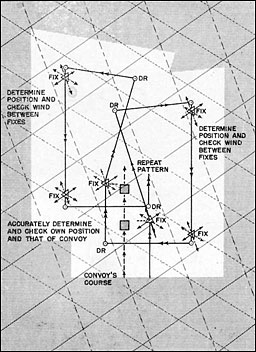
Figure 5-12.--In order to maintain the predetermined pattern or plan of air convoy escort, loran lines of position can be employed to obtain fixes for determining wind, course, speed, and the turning point required for adequate air coverage.
--143--
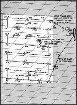
Figure 5-13.--This figure illustrates how the loran lines of position represented above by the dotted and solid parallel lines can be employed to determine the estimated positions and fixes in executing a patrol sweep of a designated area.
altitudes and loran lines of position to each aircraft. Parallel lines of position are chosen so as to maintain separation of aircraft, even under instrument conditions.
6. Traffic control.--The same principle as that applied to traffic guidance may be used to control congested traffic over an airport. Aircraft are assigned altitudes and lines of position so that each flies a definite flight pattern around or over the airport. kSeparation of aircraft at the same altitude is accomplished by assigning each a separate time difference reading for each course around the area. Radio approach channels may be guarded by designating restrictive lines of position for each channel.
For coverage of loran stations, see the Loran Chartlets contained in the appendix.
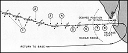 Figure 5-14.--Mine laying from high altitudes requires the use of drogue mines, which in turn require the determination of the ballistic wind. The princpal advantage of loran in mine laying are that wind and flight altitude and the heading to make good the desired course for laying the mines can be determined before coming within radar range. Consequently, during the last minutes of the run there need be only minor alterations of heading to correct for slight errors in wind or course.
Navigator takes series of loran fixes and determines accurate wind at flight altitude.
Knowing wind, altitude, and airspeed, find the necessary heading to make good the approach course. This involves solution of the ballistic problem by the navigator.
When loran homing approach can be made, preset reading and complete turn as pulses are lined up.
While homing on loran lop, check wind-drift and ground speed.
Revise ETA to release point.
Recheck ballistic problem.
Navigate by radar.
Wind and track checked by radar. Only slight alterations of heading should be necessary.
--144--
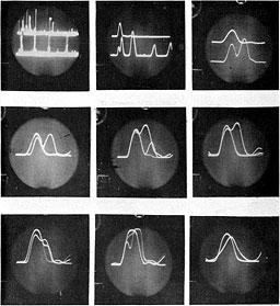
Figure 5-15.--Above is shown a group of frames taken from a motion picture showing the characteristics of loran sky waves. At the top, reading from left to right, is shown the sky-wave signals received on sweep speeds 1, 2, and 3. The middle and bottom row of photographs show the successively changing shapes of the sky waves caused by splitting as a match, on sweep speed 4, is attempted.
--145--
Table of Contents
Previous Part (4)
Next Part (6)


