PART SIX
RADIO ALTIMETERS
--147--
[BLANK PAGE]
--148--
PART SIX RADIO ALTIMETERS
THEORY AND PRINCIPLES OF OPERATION
I. GENERAL
The radio altimeter is an electronic aircraft instrument designed to indicate an aircraft's absolute altitude above the surface of the earth from zero to 4,000 feet.
The time required for a special radio signal to travel from the aircraft to the earth below and be reflected back to the aircraft is measured by the electronic equipment. Since the elapsed time is directly proportional to the distance traveled, the equipment converts this measurement into a direct altitude indication.
A transmitter and receiver are the main components of the radio altimeter. They generate and receive all the signals required for altitude measuring.
The altitude indicator shows the absolute altitude of the aircraft directly in feet, by needle deflection. Another altitude indication is provided by a limit switch and limit lights. By watching these limit lights, the pilot can fly at a predetermined, fixed altitude. This is done by setting the limit switch to the altitude that it is desired to maintain. Any altitude between 50 and 300 feet-at 25-foot intervals can be selected (AN/APN-1 has additional range settings of 500 and 3,000 feet, at 250-foot intervals). As long as the aircraft's altitude is within 10 feet of the limit switch setting, a white indicator light glows (100 feet for 400- to 4,000-foot range). If the aircraft rises more than 10 feet above the limit switch setting, a green light glows (100 feet for 400- to 4,000-foot range). If the aircraft falls more than 10 feet below the limit switch setting, a red light glows (100 feet for 400- to 4,000 foot range).
II. PRINCIPLES OF OPERATION
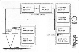
An electronic altimeter system, shown diagrammatically in figure 6-1, comprises the following elements:
-
A transmitter unit:
F-M transmitter and audio oscillator.
-
A receiving unit:
Balanced detector and audio amplifier.
-
An indicator unit:
Indicator counter.
Indicator amplifier.
Altitude meter.
Limit counter.
Limit amplifier and relay.
Limit switch.
Limit lights.
-
Transmitting and receiving antennas.
NOTE.--Excepting for the difference in altitude ranges which they indicate AN/ABN-1, 0 to 400 feet; (AN/APN-1, 0 to 400 and 400 to 4,000 feet), the two electronic altimeter equipments now in use employ the same fundamental principles of operation. (fig. 6-1.)
Referring to the block diagram, the audio oscillator generates an audio frequency signal of 120 cycles per second which is fed into the transmitter.
The transmitter generates a radio signal of constant amplitude. The frequency of the transmitter signal is controlled by the audio oscillator signal so that, 120 times per second, its frequency is varied from 420 to 460 megacycles, and back to 420 megacycles continuously on the 0- 400-foot range (and from 443 to 447 megacycles and back, on the 400- to 4,000-foot range). Because the transmitter signal is constant in amplitude but varying in frequency, it is said to be "frequency modulated." This frequency modulated signal is fed to both the balanced detector and the transmitting antenna.
Each of the antennas consist of a dipole, usually mounted under the wing or fuselage. The transmitting antenna radiates energy in all directions broadside to the dipole, but very little from its ends. Since the wing or fuselage acts as a reflector, most of the energy is radiated downward, and, on striking the earth, is reflected back to the aircraft where if is received
--149--
 Figure 6-1.--This block diagram of the AN/APN-1 series of electronic altimeter equipments illustrates generally the function of the system. The transmitting units furnish a frequency modulated signal variable over a specific band to the transmitting antenna and to the receiver. The signal is directed downward to the terrain where it is reflected back to the receiving antenna and to the receiver. Since a measurable period of time has been consumed in the travel of the signal, its frequency will differ from the signal frequency then being generated. This difference frequency will vary in accordance with time or altitude. The receiving section converts the difference frequency into terms of electric current whose values are proportional to altitude. The indicating sections register the altitude in terms of feet on the meter and in terms of altitude limits on the limit lights.
by a receiving antenna. The time taken for the energy to travel down to earth and back again is directly proportional to the absolute altitude of the airplane.
From the receiving antenna, the energy travels to the balanced-detector, which at the same time, is receiving signals direct from the transmitter. The transmitter is constantly changing in frequency. At one instant of time, it sends a signal of one frequency to the transmitting
antenna. By the time the signal reaches the ground and is reflected back to the aircraft, a definite time has elapsed, and the transmitter is now generating a new frequency. The higher the aircraft is from the ground, the longer it takes for the signal to travel down to the earth and back, and the greater difference there is between the frequencies of the two signals being fed to the receiver.
The balanced detector mixes the two signals- the one coming directly from the transmitter and the one reflected from the earth-and produces a third signal, equal to the frequency difference of the two. This difference frequency is amplified by two audio amplifier stages.
From the audio amplifier, the signal, sinusoidal in wave form, goes to the limiter, which also amplifies and, at the same time, clips off both the top and bottom so as to produce a square wave. The reason for amplifying, then clipping, the difference frequency is to insure that the amplitude of this square wave is always the same, regardless of the strength of the
--150--
reflicted signal. Thus, changes in altitude will vary the frequency but not the amplitude of the square wave.
From the limiter, the square wave goes to two circuits-the indicator counter and the limit counter. These counter circuits produce currents proportional to the frequency of the square wave fed to them, and thus proportional to the aItitude of the airplane.
Current from the indicator counter circuit is fed to a milliampmeter, which is calibrated in feet, to indicate the absolute altitude of the airplane. Current from the limit counter circuits controls two relays which turn the limit lights on and off as the altitude varies beyond the limits set by the setting of the limit switch.
When used in conjunction with an automatic pilot system, the radio altimeter can be set for automatic operation, causing the altimeter to assume flight control of the aircraft within limits defined by the presetting of the limit switch.
--151--

AN/APN-1
--152--
AN/APN-1
NOTE.--AN/APN-1 is a two-range (o-40o: 400-4,000 feet) radio altimeter whose source of supply is 27 volts (1. c. AN/APN-1A is similar in all respects to AN/APN-1 excepting that it uses a single range indicator which can lie adapted for dual range indication by the addition of an appropriate external switching device. AN/APN-1B is a two-range radio altimeter intended for special duty in connection with other equipments. AN/APN-IX is similar to AN/APN-1 in all respects excepting that its source of supply is 13.5 volts d. c.
I. FUNCTION
A. PRIMARY PURPOSE. AN/APN-1 is an aircraft radio altimeter which will indicate the absolute altitude of an aircraft between the limits of 0 to 4,000 feet, in two ranges: 0 to 400 feet, and 400 to 4,000 feet.
B. SECONDARY USES. AN/APN-1, in addition to indicating the altitude of an aircraft, will also operate to furnish visual indication of an aircraft's deviation from, or maintenance of, a preset value of altitude.
By suitable connection to an automatic pilot system, the AN/APN-1 may be used to control the altitude of flight with reference to any preset altitude, as determined by the setting of an altitude limit switch, in steps of 25 feet from 50 to 300 feet inclusive, and in steps of 25 feet from 500 to 3,000 feet inclusive.
II. DESCRIPTION
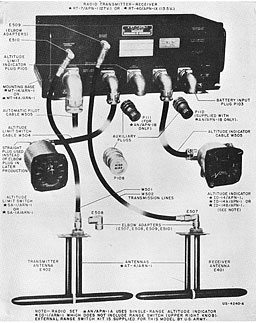
A. MAIN COMPONENTS. The AX/APN-1 consists of the following units:
-
Radio transmitter-receiver.
-
Two dipole antennas.
-
Altitude indicator meter.
-
A bank of three altitude limit lights.
-
An altitude limit switch.
-
Connect ing cables.
B. MODE OF OPERATION. 1. Altitude calibrated current meter.--The AN/APN-1 series of radio altimeters employ a frequency-modulated transmitter to generate a constantly changing radio frequency wave (constant in amplitude) which is directed toward the earth by a transmitting antenna. A reflected wave returns from the earth, is picked up by a receiving antenna and passed along to the receiver section of the equipment. At any one instant of time there will be a difference in frequency between the reflected wave and the transmitted wave. This frequency difference will be proportional to the time (distance) required for the wave to travel from the aircraft, to the earth, and back again to the aircraft.
Suitable circuits in the receiver convert this frequency difference into values of current whose strength is proportional to altitude. The current indicating meter is calibrated in terms of feet of altitude.
2. Altitude limit lights.--An additional indication of levels of altitude is obtained through the use of current-relay-operated altitude limit lights. When an altitude limit switch is set for any given altitude within the range of the equipment (in steps of 25 feet for the low range and 250 feet for the high range), relay switches, affected by changing values of current, will operate to cause indicator lights to glow.
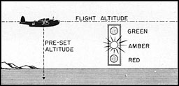
If the aircraft maintains the preset limits of altitude, a white light glows. If the aircraft's altitude rises above the preset limit, a green light glows. If the aircraft's altitude falls below the preset limit, a red light glows. See figure 6-2.
 Figure 6-2.--So long as the aircraft maintains an altitude equal to the value preset by the altitude limit switch, an amber light will glow. If the aircraft deviates more than 25 feet from this preset altitude a red light glows for decreased altitude and a green light for increased altitude.
--153--
Table of Contents
Previous Part (5)
Next Part (Appendix)


