
PART FOUR
RECOGNITION--THEORY AND PRINCIPLES
--111--
[BLANK PAGE]
--112--
RECOGNITION--THEORY AND PRINCIPLES
I. GENERAL
Recognition is the process of determining the friendly or enemy character of another.
Identification is that process of indicating your friendly character.
IFF (I-dentification, F-riend or F-oe) is an electronic system installed in ships, aircraft and shore facilities to recognize friendly contacts made by radar.
All naval aircraft (excepting trainers) and commercial aircraft under contract to the Navy for transport operations are equipped with electronic devices which automatically reply to challenges from friendly shore-based, shipboard or air-borne electronic interrogators.
II. TYPES
Basically, IFF equipment may be divided into two broad classifications:
1. Transpondors--air-borne electronic equipments which only respond to challenges, to establish the friendly character of the challenged aircraft.
2. Transpondor-interrogator-responsors--airborne equipments which not only respond to challenges but, in addition, can be used to interrogate targets to determine their identity, displaying the response, if any, on a scope screen.
III. MARK III SYSTEM
In the Mark III system (currently in use), when a detected radar target is to be interrogated, land-based or shipboard equipment transmits challenging pulses.
In the challenged target, such as an aircraft, the reception of these challenging pulses will trigger the transpondor into operation, which then transmits a coded reply to establish its identity for as long as it is challenged. At the challenging station, both the radar echoes and the IFF signals from the target are displayed.
In addition to responding to challenges to establish their own identity, air-borne equipments AN/APX-2 or AN/APX-8 can initiate challenges to interrogate and identify targets detected by their associated radars.
IV. TARGET ECHO AND IFF DISPLAY
Pulses from an aircraft's interrogator-responsor are transmitted at the same time as its radar pulses. The radar pulses are beamed direct ionally toward the target, which returns weak echo pulses. This occurs at the radar pulse-and-echo frequency.
At a much lower frequency, the interrogator-responsor transmits its pulses omnidirectionally (except AN/APX-8, which has a directional antenna system). At the target, reception of these challenging pulses will trigger the target's transpondor into action ("if it is friendly), causing it to transmit, in turn, powerful omnidirectional pulses. See figures 4-1 and 4-2.
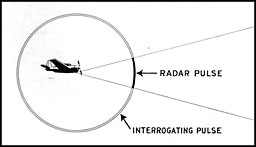
Figure 4-1.--The interrogator part of the I-R unit, when put into operation,
sends out challenging pulses along with the radar pulses.
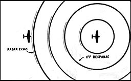
Figure 4-2.--Radar pulses return as target echoes, but the I-R challenging pulses trigger off
the target's transpondor (if it has one). Its transponder then sends back a coded reply.
--113--
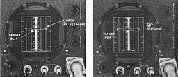
Figure 4-3.--Above is shown the IFF response as it appears on the L-type (ASB) scope.
A coded series of wide or narrow blips appear just above the target blip.
Back in the challenging aircraft, the IFF equipment, which is tuned not to the radar frequency but only to the I-R (interrogator-re-sponsor) frequency receives the omnidirectional signals.
In operation, the tuning mechanism is swept automatically through a wide band of frequencies about once every 3 seconds. Therefore, once every 3 seconds at some particular point during the sweep the responsor will be tuned to accept the frequency of the signal re-
turning from the challenged transpondor. The signal output of the IFF receiver in the challenging aircraft is fed directly to the radar indicator where it is displayed on the scope as a characteristic IFF signal, together with the radar echo.
Since IFF reception is nondirectional (excepting with AN/APX-8), the IFF signal is displayed on the scope correctly with respect only to the target's range-not its bearing. See figures 4-3 to 4-6, inclusive.

Figure 4-64.--Here's the IFF display on the APS-4 air-borne radar scope.
When land masses or other large targets interfere with just beyond the target blip.
It is correct with respect to range only, not azimuth.
--114--
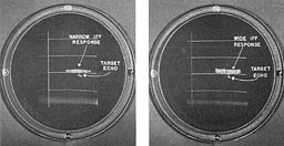
Figure 4-5.--IFF responses on the B-type appear as narrow or wide horizontal images
located just above the target image.
V. CODING
Depending upon the setting of a code selector switch, electronic circuit constants within a transpondor cause it to reply to challenges at varying pulse durations for each of the sweeps. Thus, at the challenging station, the target's
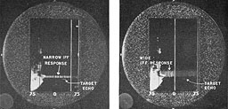
Figure 4-6.--Here's the IFF display on the APS-4 air-borne radar scope. When land masses or other large targets interfere with the observation of the IFF signal, the "gain" is reduced to wipe out the radar target, allowing the IFF signal to be clearly displayed.
--115--

Figure 4-7.--Emergency (very wide) IFF signals as displayed on the L-scan (left),
B-scan (center), and PPI-scan (right) indicator scopes.
IFF reply is viewed on the scope as a sequence of separate responses of varying widths, one each 3 seconds, which repeat themselves in series of four. The codes available are:
| Selector switch |
Code widths |
| Position 1 |
NARROW |
NARROW |
NARROW |
NARROW |
| Position 2 |
NARROW |
BLANK |
NARROW |
BLANK |
| Position 3 |
NARROW |
NARROW |
NARROW |
BLANK |
| Position 4 |
NARROW |
NARROW |
WIDE |
WIDE |
| Position 5 |
NARROW |
BLANK |
WIDE |
BLANK |
| Position 6 |
NARROW |
NARROW |
WIDE |
BLANK |
Recognition of a friendly target is thus insured by the fact that:
-
It returns an IFF response to a challenge:
-
2. The signal itself is gap-coded in accord ance with codes established by fleet doctrine.
VI. TRANSPONDOR OPERATION
1. A-band.--Normal transpondor operation occurs on a band of frequencies from 157 megacycles to 187 megacycles, designated as the A-band.
2. G-band.--Certain aircraft (VF), in addition to establishing their identity to search radars on the A-band, must be quickly recognized by fighter-director activities. As the result of specific voice-radio requests, such VF aircraft transpondors can be switched from the normal A-band operation to a designated fixed frequency in the G-band of frequencies (194 megacycles to 212 megacycles), its G-band responses being displayed on the fighter director's PPI scope onlv.
3. Emergency.--In aircraft in distress, the IFF equipment can be set to respond to challenges so as to return pulses of exceptionally long duration once every 3 seconds. These are viewed on the scope (fig. 4-7) at the challenging station as very wide IFF signals, establishing the fact that the interrogated aircraft is in distress.
VII. INTERROGATOR-RESPONSOR OPERATION
The interrogator-responsor unit transmits challenges to other craft and receives replies from those that are equipped with the proper transpondor units. The frequency range of the I-R (interrogator-responsor) unit is 160 megacycles to 184 megacycles, and, while the interrogator and the responsor have separate tuned circuits they are normally tuned to the same frequency. Tactical considerations determine the exact frequency within this band, designated for use in a specific area or for a specific length of time.
--116--
[BLANK PAGE]
--117--
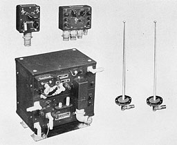
AN/APX-2
--118--
AN/APX-2
(Transpondor-lnterrogator-Responsor)
I. FUNCTION
A. PRIMARY PURPOSE. The two basic purposes of the equipment are to enable the aircraft in which it is installed:
1. To identify itself as friendly when it is challenged by appropriately equipped air, ship, and ground forces.
2. To challenge a radar contact to determine its friendly or enemy character.
B. SECONDARY USES. 1. AN/APX-2 can be used by aircraft in distress to transmit an emergency reply to interrogating stations. The character of the emergency signal as viewed on the scope of the interrogating stations indicates that the aircraft interrogated is in distress.
2. As the result of voice-radio instructions from CIC intercept officers, AN/APX-2 can be set for G-band transmission-a mode of operation wherein a 5-cycle blinking signal is transmitted on a specially designated frequency. The display of the G-band signal on the intercept officer's PPI scope furnishes an additional mode of aircraft identification and enables the intercept officers to differentiate between the aircraft so interrogated and others in the same group.
3. A further supplementary purpose of the equipment is to enable the aircraft in which it is installed to serve as a beacon on which other appropriately equipped aircraft can "home."
II. DESCRIPTION
A. MAIN COMPONENTS. AN/APX-2 consists of:
-
Two fixed, rodlike antennas, one for
transpondor operation, the other for interrogator-responsor operation.
-
Transpondor unit.
-
Interrogator-responser unit.
-
Pilot's control unit.
-
Operator's control unit.
-
Impact destructor switch.
-
Connecting cables.
The transpondor and the interrogator-responsor form one unit of equipment. The top chassis of this unit contains the two-channel (A band and G/R, band) transpondor and the bottom chassis contains the interrogator-responsor unit.
Receptacles are provided in the unit for screw-in destructors which can be exploded by throwing the destruct switch in the pilot control unit when there is danger of the equipment's falling into enemy hands. The impact destructor switch furnishes additional means for exploding the destructors by operating automatically upon impact, as in the case of a crash landing.
B. MODE OF OPERATION. 1. Method of identification.--The presence but not the identity of aircraft, ships, etc., may be detected over considerable distances by means of radar equipment. It is the function of IFF equipment to supplement radar detection and; location by challenging the unknown craft for recognition as friend or foe, and conversely, to furnish identification upon challenge from other friendly craft. The operative method employed by IFF equipment is the transmission and reception of very short spurts (pulses) of continuous-wave radio-frequency energy. General identification as "friendly" is accomplished as follows:
The challenging craft (or shore facility), after making radar contact, transmits a series of "interrogating" pulses.
On reception of this series of interrogation pulses, the challenged craft (if appropriately equipped) automatically transmits a series of reply pulses, which are coded for special identification or tactical purposes.
The coded reply is received by the challenging craft and displayed on the screen of a cathode-ray tube so that the coded sequence of IFF signals may be observed readily.
The failure of an unknown craft to make a proper IFF reply, after it has been located by radar and challenged by IFF, classifies it as unidentified, and hence presumably an enemy.
2. Associated equipment.--Since AN/APX-2 equipment is designed to transmit challenges and receive replies, as well as to receive challenges and transmit replies, the use of associated radar or other indicator equipment is required. The IFF responses it receives may be combined with the radar display or viewed on a separate
--119--
indicator used to display IFF responses only. IFF responses indicate the range hut not the azimuth bearing of the replying craft, so that exact recognition must be made by means of range associations between IFF responses and radar echoes.
3. Beacon function.--For the supplementary beacon use of the equipment, the same procedure of challenge and reply is followed, but the challenging or "homing" craft must be equipped with a directional antenna system so that accurate bearings can be taken on the aircraf t.that is employing the beacon operation of its AN/APX-2 equipment.
C. SPECIAL FEATURES. 1. Transpondor.--The upper chassis of AN/APX-2 is a two-channel (A- and G/R-band) transpondor unit which receives challenges and automatically transmits replies. The G/R-band tuning unit is included as an integral part of this chassis, but it is designed so as to be removable, and replaceable by a similar unit operating in a different frequency channel. This alternative tuning unit is not supplied as part of the AN/APX-2 equipment and is not discussed herein.
a. A-band.--The tuned circuit of the A band is motor-swept from 157 megacycles to 187 megacycles during a sweep period of 2½ seconds, following which there is a brief sweep-retrace of "flyback" interval (approximately one-third of a second in duration) before a new frequency sweep is begun. During the sweep, itself, interrogation pulses (challenges) can be received on any frequency in the A-band range, and reply pulses will be automatically transmitted, pulse for pulse, on the same frequency. These A-band replies are coded, so that in addition to providing general identification responses, the replies also may be used to communicate tactical information based on a predetermined code schedule.
Coding is accomplished by means of selected combinations of narrow pulses, wide pulses, and blanks. Four sweeps, or about 11 seconds, are required to transmit a code combination. Six combinations are available as determined by the setting of the selector switch on the operator's control unit.
The A-band also may be used for emergency operation, during which it transmits very wide ("distress") pulses which the challenging craft will immediately recognize as an urgent appeal for help.
b. G/R-band.--The separate tuned circuit of the G/R band is normally preset to a designated operating frequency within the G-band frequency range of 194 megacycles to 212 megacycles. However, by means of a bench adjustment (plugging in a "Rooster" capacitor), this tuned circuit may be preset to a designated operating frequency in the "Rooster" (IFF beacon operation) range of 172 to 182 megacycles. In either case, interrogation pulses are received only on the preset frequency, and replies are automatically transmitted, pulse for pulse, on the same frequency.
Neither G band nor Rooster band replies are coded, as the operating frequency chosen serves for special identification.
G-band operation is not used as a substitute for A-band (general identification) operation, but serves as an additional function for special fighter plane control purposes.
Rooster band operation is used only for the special "beacon" purpose.
c. Concurrent operation A-G bands.--Concurrent operation of the A and G bands is made possible in the equipment by sharing operating time. The time-sharing circuit cycles at the rate of about 5 c. p. s., alternately switching the A-band off and on. while simultaneously switching the G-band on and off. so thai the G-band and A-band operate alternately for intervals of approximately one-twentieth and three-twentieths of a second, respectively.
Time-sharing operation of the two bands is initiated whenever the G-band -witch is thrown on while the A-band is operating (master control switch in the Norm position).
Time-sharing begins immediately, but does not cease the instant the G-band switch returns to its OFF position. A "holding" circuit ensures the continuation of G-band (time sharing) operation for an interval of 10 to 20 seconds.
d. Rooster function.--When the G/R band has been adjusted and is used for Rooster operation, it operates continuously and the A-band is switched off.
e. Transpondor suppression.--All transpondor
--120--
operation (A-band alone, A and G bands sharing time, or Rooster alone) is suppressed during the very brief operative periods of the interrogator-responsor in the lower chassis. Additional suppression is also available, when required, to avoid interference with the operation of associated equipment.
NOTE.--It should be emphasized that the use of the word "operation" in connection with the transpondor unit does not necessarily imply that the transpondor is actually receiving challenges and transmitting replies. It is convenient to speak of "transpondor operation," but this means only that the transpondor is in an operative state; I. e., it is able to receive interrogations and transmit replies whenever and as long as it is actually challenged. If no challenges are received, nothing is transmitted (unless strong electrical noises should cause the transmission of false replies-a condition called "squittering"). On the other hand, when the transpondor is inoperative or suppressed, it is disabled from receiving challenges and from transmitting either true or false replies. Since the transpondor operates automatically (when it is in an operative state and challenged), the pilot and/or operator are relieved of the intolerable burden of making control adjustments every time their craft is challenged. Their craft may be continuously challenged and will continuously transmit replies without their even being conscious of it. Indeed, the only check they have on whether or not the transpondor is actually operating (once the controls have been set to put it in an operative state) is to plug headphones in the phone jack on the transpondor unit and listen for the characteristic sounds produced by received interrogations and transmitted replies in the various types of transpondor operation.
2. Interrogator-responsor.--a. Mode of operation.--The interrogator-responsor unit is located in the lower chassis of the AN/APX-2. This unit transmits challenges to other craft
and receives identification replies from those that are equipped with the proper transpondor units. The frequency range of the I-R unit is 160 to 184 megacycles, and while the interrogator and responsor have separate tank circuits, they are normally tuned to the same frequency. Tactical considerations and fleet doctrine determine the exact frequency designated for use in a specific area or for a specified length of time.
b. Interrogator.--Normally the interrogator-responsor unit is not kept in continuous operation (as is the A-band transpondor), but is thrown into operation by use of the INT switch, whenever the pilot or operator wishes to challenge an unknown craft whose presence is detected by radar or suspected.
c. Responsor.--The responsor is inoperative except for a brief "receptive period" immediately following each transmitted interrogation pulse. In high-power operation, the length of this receptive period is approximately 1250 microseconds, and in low-power operation it is approximately 125 microseconds. During these periods the responsor is enabled to receive reply pulses from challenged craft. The received replies are directed, amplified and delivered to the cathode-ray tube circuits of the associated radar or indicator equipment.
During each interval the interrogator-responsor is transmitting and receiving, all transpondor operation in the upper chassis is suppressed.
III. TACTICAL EMPLOYMENT
Refer to page 126.
--121--
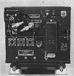
AN/APX-1
(Transpondor)
AN/APX-1
(Transpondor)
I. FUNCTION
A. PRIMARY PURPOSE. AN/APX-1 is employed in aircraft for the purpose of receiving challenging signals from friendly ground forces, surface vessels and aircraft, and responding with a coded reply signal which identifies the aircraft in which it is installed as friendly.
B. SECONDARY USES. A supplementary use that can be made of the equipment-not possible unless an auxiliary control unit is used-is to enable aircraft in which it is installed to serve as a beacon on which other aircraft having suitable interrogation equipment (such as AN/APX-2 or AN/APX-8) may "home."
II. DESCRIPTION
A. MAIN COMPONENTS. The AN/APX-1 consists of the following:
-
A single, fixed, rodlike antenna.
-
A transpondor unit (receiver-transmitter).
-
Power supply unit.
-
Pilot's remote control unit.
-
Pilot's auxiliary control unit.
-
Selector unit.
-
Impact switch.
B. MODE OF OPERATION. Prior to flight, the selector switch unit is adjusted to provide proper coding as determined by fleet doctrine.
Control of the equipment is by means of the auxiliary and remote control switch units located in the pilot's cockpit.
In operation, the AN/APX-1 is similar in all respects to that of AN/APX-2, with one main exception; it will only reply to interrogations from other friendly craft (transpondor operation). It does not contain an interrogator-responsor unit and cannot challenge other aircraft.
(For transpondor operation of AN/APX-1, see Transpondor, AN/APX-2, p. 103.)
III. TACTICAL EMPLOYMENT
Refer to page 126.
--122--
[BLANK PAGE]
--123--
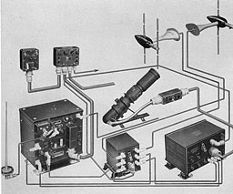
AN/APX-8
--124--
AN/APX-8
(Transpondor and Directional Interrogator-Responsor)
I. FUNCTION
A. PRIMARY PURPOSE. AN/APX-8 is an electronic identification equipment used for the purpose of interrogating radar-detected targets, and displaying the IFF response (if any) on its own scope screen to indicate the target's general bearing, as well as its range and identity. It can be used in non-radar equipped aircraft, or where a separate display of IFF signals is desirable.
II. DESCRIPTION
A. MAIN COMPONENTS. AN/APX-8 consists of a complete AN/APX-2 installation (see p. 106) plus the following AN/APA-1 units:
-
Control box.
-
Remote indicator-amplifier.
-
A viewing scope.
-
An antenna switching unit.
-
Two fixed directional antennas.
B. MODE OF OPERATION. 1. Directional feature of AN/APX-8.--The AN/APX-2 part of the installation functions as before:
(a) To respond to interrogations from other craft (transpondor operation).
(b) To interrogate other craft and display the response on the scope of the parent radar. Because of the omnidirectional radiation and reception characteristics of AN/APX-2, the visual response appears on the radar scope correct only with respect to range and identity. The bearing of the target is not indicated. If, for example, two targets are at the same range but at different bearings, a single IFF response will indicate that one is friendly while the other ostensibly is a bogey (or skunk). But lacking bearing information it will not be possible to identify the friendly from the bogey.
With the addition of the AN/APA-1 equipment to the AN-APX-2 installation, (making the combination an AN/APX-8), the interrogator's challenging signals are transmitted di-rectionally toward an observed radar target by turning the aircraft in the direction of one of the radar targets. The response (if any) appears on the APA-1 L-scan type of scope. The lateral disposition of the response blip on the trace indicates the bearing of the target furnishing the response, relative to the interrogating aircraft's heading. See figures 4-8 and 4-9.
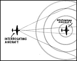
Figure 4-8.--Directional antennas and a lobe-switching device on the interrogating aircraft equipped with AN/APX-8 enable it to receive the IFF responses from the target aircraft and determine its relative bearing.
2. Operating ranges.--AN/APX-8 can be set for any one of three operating ranges of 5, 50, and 100 miles by the use of a 3-position toggle switch located on the control unit.
A plexiglass scale, located over the face of the AN/APA-1 viewing scope assists in judging the approximate range of a target's IFF response.
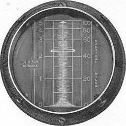
Figure 4-9.--The IFF response as displayed in the APX-8 indicator.
When the target is dead ahead, the IFF blip appears centered about the trace.
--125--
III. TACTICAL EMPLOYMENT
See below.
TACTICAL EMPLOYMENT OF IFF
I. FACTORS APPLICABLE TO TACTICAL EMPLOYMENT OF ALL MARK III IFF EQUIPMENT
1. The Mark III IFF equipment is an aid in determining the friendly or enemy character of a target, and cannot be relied upon to give 100 percent identification. All possible means of recognition are to be used in conjunction with IFF, particularly in regard to planes operating in battle areas. Operating personnel must be alert to the limitations of the IFF system, and support it with an up-to-the-minute understanding of the existing tactical situation. It must also be realized that the mere fact that one's own ship has identified the target is no proof or assurance that the target has identified the ship. IFF is an additional means of identification; all other means of identification and recognition must be used with special emphasis being placed on alert lookouts.
2. Although six different codes (exclusive of the emergency indication) are available, their characteristics are such that they are not readily distinguishable when two or more transponders are operating at approximately the same range. Their characteristics depend on a combination of wide and narrow blips occurring during a 12-second cycle. Thus, when a large number of transpondors are in operation a confused picture is presented to the radar operator. Practically, under these conditions the radar operator can recognize that responses consist of:
-
All narrow blips.
-
A combination of narrow and wide blips.
-
Emergency signals.
When operating ship-borne radar equipment on long range (375 miles), distinction between narrow and wide blips is difficult, and emergency signals (very wide) are the only ones readily identified.
3. At the present time IFF antennas have either very limited directional characteristics or are entirely nondirectional, and replies should be expected over a wide variation in bearing. Thus it is possible for an enemy contact to be indicated as friendly if it is at the same range as a friendly craft on a different bearing. Due to this bearing limitation, the Mark III has no reliable value in a melee. In view of the above, it must be realized that the bearing resolution of IFF is nonexistant for all practical purposes, and that the range resolution is the only sure means of determining whether an IFF response is emanating from a given target. The range resolution of IFF in most cases is determined by the radar display and therefore every effort should be made to use the most expanded scope available.
4. There is a possibility that the effectiveness of transmissions of transpondors or interrogators may be reduced by either ship or aircraft structure in the proximity of the associated antennas.
5. In the air, pilots are normally unable to determine definitely whether their transpondor is functioning properly.
6. A sense of false security must not be permitted because many friendly blips from a group of planes can be seen on the radar screen. It is quite possible for enemy planes to trail such a group and attempt to take advantage of their transpondors to press home an attack. It is also possible for blips from friendly aircraft to conceal blips from enemy surface craft.
7. The possibility that the transpondor on a challenged ship or plane may be out of commission or may not be turned on must always be considered.
8. The possibility that the enemy may have similar or captured equipment must be considered.
9. It is necessary, in areas which are known or believed to be within the coverage of enemy radar apparatus and which are also covered by friendly radar, to strike a balance between the advantage of keeping IFF switched on to assist identification of friendly forces as compared to danger which may arise from detection of IFF by the enemy. It is to be noted that several known types of Japanese surface and air-borne radars will trigger the Mark III IFF, and that use of transpondors when in the vicinity of known enemy short installations or major fleet units must be goverened accordingly. Moreover, the advantages of positive identification to friendly submarines must be recognized.
--126--
Table of Contents
Previous Part (3)
Next Part (5)


