
PART TWO
RADAR SYSTEMS
| |
Page |
| PRINCIPLES OF OPERATION OF THE RADAR SYSTEM |
| I. |
General |
11 |
| II. |
Types of Scope Presentation |
12 |
| |
A. |
Blip Type |
13 |
| |
B. |
Spot Type |
13 |
| III. |
Range Measurement |
18 |
| IV. |
Factors Which Limit all Radar Performance |
19 |
| |
A. |
Variable Factors |
19 |
| |
B. |
Constant Factors |
29 |
| EQUIPMENTS |
| ASB SERIES |
| I. |
Function |
33 |
| |
A. |
Primary Purpose |
33 |
| |
B. |
Secondary Uses |
33 |
| II. |
Description |
33 |
| |
A. |
Main Components |
33 |
| |
B. |
Antenna Scan and Scope Presentation |
33 |
| |
C. |
Improvements Incorporated in Later ASB Equipments |
35 |
| III. |
Tactical Employment |
36 |
| |
A. |
Search |
36 |
| |
B. |
Navigation |
38 |
| |
C. |
Radar Bombing and Torpedo Laying |
38 |
| AN/APS 15 |
| I. |
Function |
41 |
| |
A. |
Primary Purpose |
41 |
| |
B. |
Secondary Uses |
41 |
| II. |
Description |
41 |
| |
A. |
Main Components |
41 |
| |
B. |
Antenna Scan and Scope Presentation |
41 |
| |
C. |
Special Features |
42 |
| III. |
Tactical Employment |
45 |
| |
A. |
Search |
45 |
| |
B. |
Navigation |
47 |
| |
C. |
Bombing |
48 |
| AN/APS-15A AND AN/APS-15B |
| A. |
Special Features of AN/APS-15A and AN/APS-15B |
49 |
| ASG AN/APS-2 SERIES |
| I. |
Function |
52 |
| |
A. |
Primary Purpose |
52 |
| |
B. |
Secondary Uses |
52 |
| II. |
Description |
52 |
| |
A. |
Main Components |
52 |
| |
B. |
Antenna Scan and Scope Presentation |
52 |
| III. |
Tactical Employment |
53 |
| |
A. |
Search |
53 |
| |
B. |
Navigation |
53 |
| |
C. |
Bombing |
53 |
| AN/APS-3 |
| I. |
Function |
55 |
| |
A. |
Primary Purpose |
55 |
| |
B. |
Secondary Uses |
55 |
| II. |
Description |
55 |
| |
A. |
Main Components |
55 |
| |
B. |
Antenna Scan and Scope Presentation |
55 |
| |
C. |
Special Features |
57 |
| III. |
Tactical Employment |
58 |
| |
A. |
Search |
58 |
| |
B. |
Navigation |
59 |
| |
C. |
Bombing |
59 |
| AN/APS-4 |
| I. |
Function |
61 |
| |
A. |
Primary Purpose |
61 |
| |
B. |
Secondary Uses |
61 |
| II. |
Description |
61 |
| |
A. |
Main Components |
61 |
| |
B. |
Antenna Scan and Scope Presentation |
61 |
| |
C. |
Special Features |
61 |
| III. |
Tactical Employment |
63 |
| |
A. |
Search |
63 |
| |
B. |
Navigation |
63 |
| |
C. |
Bombing |
63 |
| |
D. |
Intercept |
64 |
| AN/APS-6 SERIES |
| I. |
Function |
67 |
| |
A. |
Primary Purpose |
67 |
| |
B. |
Secondary Uses |
67 |
| II. |
Description |
67 |
| |
A. |
Main Components |
67 |
| |
B. |
Antenna Scan and Scope Presentation |
67 |
| |
C. |
Special Features |
70 |
| III. |
Tactical Employment |
70 |
| |
A. |
Search |
70 |
| |
B. |
Intercept |
72 |
| |
C. |
Gun Aim |
72 |
| |
D. |
Navigation |
72 |
| GENERAL APPLICATIONS OF RADAR |
| I. |
Introduction |
75 |
| II. |
Reconnaissance and Patrol |
75 |
| |
A. |
General |
75 |
| |
B. |
Area Search |
75 |
| |
C. |
Sector Search |
77 |
| |
D. |
Anti-Submarine Search |
77 |
| III. |
Navigation |
77 |
| |
A. |
Drift |
77 |
| |
B. |
Absolute Altitude |
80 |
| |
C. |
Coastal Navigation |
80 |
| |
D. |
Mine Laying |
80 |
| IV. |
Radar Bombing |
81 |
| |
A. |
Low-Altitude Bombing |
81 |
| |
B. |
High-Altitude Bombing |
83 |
| AIR-BORNE TAIL WARNING RADARS |
| I. |
Types and Function |
85 |
| ASSOCIATED EQUIPMENTS |
| AN/APA-16 |
| I. |
Function |
87 |
| II. |
Description |
87 |
| III. |
Mode of Operation |
87 |
| AN/APQ-5B |
| I. |
Function |
91 |
| II. |
Description |
91 |
| III. |
Mode of Operation |
91 |
| IV. |
Performance Characteristics |
92 |
| AN/APG-4 |
| I. |
Function |
95 |
| II. |
Description |
95 |
| III. |
Mode of Operation |
95 |
| IV. |
Performance Characteristics |
95 |
| AN/APG-5 |
| I. |
Function |
97 |
| II. |
Description |
97 |
| |
A. |
Main Components |
97 |
| |
B. |
Mode of Operation |
97 |
| |
C. |
Performance Factors |
97 |
--7/9--
[BLANK PAGE]
--10--
Part Two
Radar Systems
PRINCIPLES OF OPERATION OF THE RADAR SYSTEM
I. GENERAL
RADAR is a coined word. It means RA-dio Detection A-nd R-anging.
Air-borne radars perform three main functions:
1. They detect the presence of targets.
2. They indicate relative bearing of the target from the aircraft.
3. They indicate in nautical miles the range of the target from the aircraft.
Certain basic radio phenomena contribute to the function of radar:
1. Radio waves generated at ultra-high frequencies have practically the same transmission properties as light. They travel from the transmitting antenna out to the horizon, and beyond, in straight lines on a line-of-sight principle. See figure 2-1.
2. The employment of ultra-high frequencies permits the use of relatively small, compact antennas which can be designed to concentrate the transmitted radio energy in a narrow path or beam: thus directional transmission and reception is obtained. See figure 2-2.
Objects which are in the path of beamed ultra-high-frequency transmissions reflect or reradiate a small portion of the transmitted energy back to the source. See figures 2-3 and 2-5.
Together, these three phenomena form the fundamental concept on which the operation of all radars is based.
To achieve its purpose of denoting the presence, bearing and range of objects (targets), a radar system employs certain basic units:
1. The transmitter.--Unlike conventional continuous wave radio transmitters, the radar transmitter generates ultra-high-frequency radio energy which is transmitted in short bursts or pulses. The pulsing cycle of a radar transmitter would look something like that shown in figure 2-4. Each pulse is on the order of one or two microseconds in duration, with relatively long rest or quiescent periods in between pulses during which the reflected echoes are received. For instance, a transmitter which pulsed 500 times a second with 2-microsecond pulses would have a rest period in between pulses of 1,998

Figure 2-2.--Depending on the design of the antenna, the transmitter radio energy can be directed in a narrow lobe or beam.

Figure 2-1.--Radio waves generated at ultra-high frequencies have practically the same transmission properties as light waves. They travel from the source out to the horizon and beyond on a line-of-sight principle.
--11--

Figure 2-3.--In this diagram a single pulse is shown, the shaded arrows in the beam denoting the progressive positions of the outward-going pulse as it travels from the directive antenna.
microseconds. Because radio waves travel at a constant velocity of 162,000 nautical miles per second, the time (during the rest period) required for a pulse to travel out to the target and return as a reflected echo would depend upon the distance of the target from the transmitter.
2. Directional antennas.--The pulses generated by the transmitter are fed to a directional antenna which transmits them into space in a narrow beam. An object in the path of the beam will reflect back a small portion of the pulse energy. Early types of radar employed fixed directional antennas which transmitted the beam of radio energy out to either side of the aircraft, or straight ahead. Later equipments employed a movable type of antenna which could be rotated manually from abeam to ahead. The newer types employ an electrically driven antenna which either oscillates through an arc of 150° ahead of the aircraft or rotates through 360° of azimuth.
3. Receiver-indicator system.--Back on the aircraft, the reflected pulse energy is received by the antenna, amplified in the receiver and passed along to an indicator unit containing a special timing device-a cathode-ray tube- which translates into terms of range the elapsed time that it took for the transmitted pulse to go out to an object and return to the radar as a reflected echo. One the cathode-ray tube screen (scope), the range of the target is indicated by the position of the target echo on a calibrated time trace. The bearing from which an echo returns is determined by utilizing the directional characteristic of the antenna system, and synchronizing it with the scope display.
II. TYPES OF SCOPE PRESENTATION
The diagrams, figures 2-3 and 2-5, show the relationship of the indicator to the other basic

Figure 2-4.--Radar transmitters send out pulses of radio-frequency energy many times per second. These pulses vary in duration from-about ½ to 2 microseconds (millionths of a second). Depending upon the range for which the equipment is designed to operate, the quiescent or inoperative period between pulses is long enough.
--12--

Figure 2-5.--When the outward-going pulse strikes an object in its path, a small amount of radio energy is reflected back toward the source where it will be displayed on the indicator as a visual signal.
radar system units. Each time that the trans-milter furnishes a pulse to the antenna, a minute quantity of pulse energy is fed to the indicator where it is used as a timing pulse to cause a spot of light, visible on the cathode-ray tube screen, to form a time trace.
There are two methods in use by which a target echo is made to register its presence on the time trace. One method is called the "blip type" and the other is called the "spot type" indication.
A. BLIP TYPE. 1. L-scan.--Early type airborne radar equipments, such as the ASB, employ what is termed an L-type scope presentation where the spot of light, in synchronization with (he pulsing of the transmitter, appears lirst at the bottom center of the screen and moves upward vertically as the pulse travels outward through space. The recurrence and movement of the spot is so rapid that, to the eye, a vert ical bar of light, called the time trace, is formed. It is calibrated in terms of range. See figure 2-6.
Received radar echoes cause the rapidly moving spot of light to detour momentarily in its upward path to form jagged pointers of light out from the side of the trace. This is called, tlie blip type of indication, the blip appearing at a distance upward from the bottom of the trace proportional to the time that it took for the transmitted pulse to go out from the antenna, strike a target, and return to the radar in the form of a week, reflected target echo. The bearing of the indicated target is determined by noting the position of the antenna when maximum lateral length of blip is obtained.
2. A-scan.--Some equipments (ASG, AN/APS-2, AN/APS-15, etc.) employ a monitoring A-scope which is similar in operation to the L-type scope excepting that a horizontal trace is employed and signal voltages produce blips which appear up from and along the trace.
B. SPOT TYPE. Later air-borne radar equipments utilize spot-type scope displays which
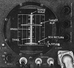
Figure 2-6.--The L-type scope is the ASB indicator. A rapidly recurring spot of light forms a vertical trace. Signal voltages applied to deflecting plates within the cathode-ray tube cause the spot to momentarily detour literally, producing the target blips.
--13--
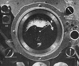
Figure 2-7.--This is the PPI-type scan. Rotating in step with the antenna a radial trace has portions of its length intensified by the reception of reflected pulses causing a pattern to be "wiped' on the face of the PPI tube. For purposes of illustration the brilliance of the trace has been increased in the scope presentation above. In actual practice the brilliance of the trace is brought up to a point to where it is barely visible.
include the PPI (circular map), the B-scan (square map), the H-scan and O-scan (double dot), and the G-scan (growing wing) types of scope presentation. Some radars use combinations of these scope presentations. (AN/APS-4 uses B-scan and H-scan: AN/APS-6 uses B-scan and G-scan.)
1. PPI-scan.--In radar equipments employing the PPI type of presentation (fig. 2-7), the dish-type antenna revolves through 360° of azimuth. On the scope screen of the indicator, the rapidly recurring spots of light form a radial time trace which rotates in synchronism with the rotation of the antenna. Target echoes are displayed on the screen as a momentary intensification in the brilliance of a portion of the revolving trace. They appear at points outward from the center of the screen, along the trace, to indicate azimuth and range of the target. Because of the persistence of the screen's fluorescent coating, the target images remain in view, diminishing in brilliance after the trace has swept past. (This type of spot presentation is found in such airborne radars as the AN/APS-2F and AN/APS-15.)
2. B-scan.--In the B-scan or square map type (fig. 2-8), a dish antenna mechanically sweeps from side to side through a 150° arc to scan a fan-shaped area ahead of the aircraft. On the scope screen of the indicator, the rapidly recurring spots of light form a vertical time trace which moves from side to side across a rectangular screen in synchronism with the antenna movement. The echo from a ship or other relatively small target will cause a momentary intensification in the brilliance of a small portion of the trace to produce a spot of light. The distance at some point upward from the bottom of the trace at which this spot appears is proportional to the target's range. Echoes from land masses or large targets will cause a correspondingly greater portion of the trace to increase in brilliance during the period of scan.
As the trace moves from side to side across the screen, its intensified portion "wipes" the target images on the scope in the form of a brilliant light pattern which, because of the relatively high order of persistence of the fluorescent screen coating, remains visible after the tract' has swept past. (This type of spot presentation is found in such air-borne radars as the AN/APS-3 and AN/APS-4.)
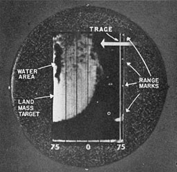
Figure 2-8.--In the B-type scan a rectangular area is covered by the vertical trace which moves from side to side in step with the scanning movement of the antenna. Target areas produce reflected echoes which intensify a portion of the trace, forming a light pattern on the scope face. Because of the relatively high persistence of the fluorescent coating on the tube face, the pattern is retained momentarily after the trace moves by.
--14--
B-scan, distortion.--In the B-scan, or square-map type of scope presentation, the fan-shaped area being scanned is represented on the scope screen as an illuminated rectangle. A fan-shaped scope screen could be provided but it would have the disadvantage of crowding targets at the apex of the triangle. Moreover, the crowding would become decidedly pronounced as the range to the target was closed, making definition of separate targets difficult if not impossible.
By virtually spreading out the apex area and producing a rectangular display, the crowding effect is overcome; but it introduces two separate distortion effects for which mental correction must be made in interpreting scope patterns on the rectangular screen.
The first distortion effect is particularly noticeable with large land-mass patterns or ships in column. See figure 2-9. Suppose that the range from the aircraft to the target dead ahead, "D," is 6 miles; the range to the other targets in column of ships would vary. To the "A" and "G," the range would be 10 miles; to "B" and "F," 8 miles; to "C" and "B," 6½ miles.
On the scope, instead of being located across the screen in a straight line, "A" and "G" would appear at the 10-mile range, "B" and "F" at
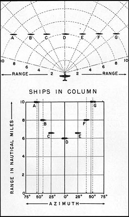
Figure 2-9.--At the top is shown a column of ships as they would appear under conditions of good visibility to an observer in an aircraft. Note the range and bearing to each of the ships. The lower half of the figure shows how these same ship targets would appear on scopes employing the B-scan display. Mental correction must be made for the apparent distortion introduced by the rectangular scan.
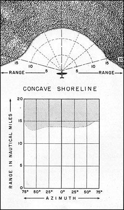
Figure 2-10.--Because the fan-shaped area being scanned ahead of the aircraft is represented as a rectangular pattern, the radar images are distorted. Here a concave shore line whose various points are approximately equidistant from the aircraft is represented on the scope as a land-mass pattern whose shore line is practically a straight line.
--15--
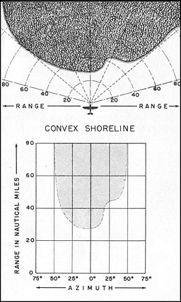
Figure 2-11.--When a shore line being scanned is irregularly convex as shown here, the scope pattern appears with an exaggerated curvature. Upon inspection, however, points of reference on the land area appear correctly with respect to range and azimuth on the scope pattern.
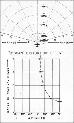
Figure 2-12.--As shown in the sketch at the top, the bearing of the ship target alters as the range is closed. On the scope, because the apex of the fan-shaped area being scanned is in effect stretched out to form a rectangle, targets to either side of dead ahead as they are approached appear to rapidly drift off to the side of the scope.
8 miles, "C" and "E" at 6½ miles, "D" at 6 miles. In other words, a straight line of ships would produce target echoes displayed on the scope in a curved line, but actually correct as to range and bearing. Unless this distortion effect is taken into consideration, it complicates the interpretation of pattern contours.
In figure 2-10, because the coast line being approached is concave, the radial distance to all points along the coast is about the same. Therefore, on the scope the coast line appears approximately as a straight line. A convex coast line, on the other hand, looks like that shown in figure 2-11.
The second distortion effect is particularly noticeable with respect to the bearing of nearby targets as the range is being closed. Targets slightly off to either side of dead ahead appear to move rapidly outward to the edges of the rectangular screen during the approach. Figure 2-12 illustrates this point.
3. H-scan.--The AN/APS-4 is one of the types of air-borne radar equipments employing the H-scan (in addition to the B-scan). When this equipment is set for Intercept, a 6° beam from the antenna scanner is made to sweep from side to side over a rectangular area ahead of the longitudinal axis of the aircraft, 150° in azimuth and 24° in vertical plane. This back-
--16--
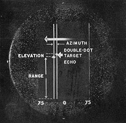
Figure 2-13.--When set for Intercept the AN/APS-4 equipment produces a scope pattern consisting of two dots (an echo and shadow pip), formed by the lateral sweep of a double trace moving from side to side across the screen.
and-forth motion takes place about 60 times a minute.
On the rectangular screen of the scope, a single trace moves from side to side in synchronism with the azimuth sweep of the scanner. With respect to the scope presentation, the position of the intercepting aircraft is considered to be at the lower center of the screen. Another aircraft within the field of the beam will reflect echoes which are displayed on the scope screen as two spots of light, termed "pips." The pip at t he left is called the echo pip, its location on the scope screen denoting the target's range and azimuth. The pip to the right of the echo pip is called a shadow pip. Its angular position with respect to the echo pip denotes the relative elevation of the target. The two pips move about on the screen together. When the interceptor aircraft is maneuvered so that the echo pip lies on the central scribed azimuth line, the target is dead ahead. When the interceptor aircraft is maneuvered so that the shadow pip is aligned horizontally with the echo pip, the target is in line with the longitudinal axis of the interceptor aircraft. See figure 2-13.
O. O-scan.--The O-type scan, whose scope presentation is somewhat similar to the H-scan, is employed in air-borne radar equipments especially designed for interception (fighter aircraft). In the O-type presentation, the scan or sweep of the antenna is produced by the combination of two movements of the spinner. One movement rapidly rotates the antenna dish 1,200 r. p. m.; the other movement sweeps the antenna assembly through 60° from dead ahead to the outer limits of the 60° angle and returns to center. This cycle occurs once every 2 seconds. As a result of these two movements, an outward-inward spiral motion is imparted to the antenna to sweep the 9° antenna beam spirally through a 120° conelike area ahead of the longitudinal axis of the aircraft.
On the O-type scope screen this antenna action is translated into the movement of two vertical traces which start at the vertical center of the screen and move outward, then inward, in synchronism with the outward and inward spiralling motion of the antenna. On the screen the opening and closing movement of the two traces is referred to as the "barn door effect."
Target echoes are of the "double-dot" presentation, similar to that obtained in the H-type scan. The azimuth position of the target is
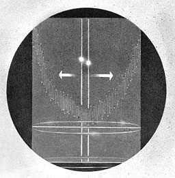
Figure 2-14.--In the O-type scan a spiralling antenna motion is translated on the scope screen into the movement of two vertical traces which start at the vertical center of the screen and move outward and inward to produce the pattern shown here.
--17--
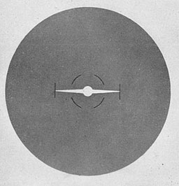
Figure 2-15.--The G-type or gun aim scan produces a spot of light when a target is within range of the conical antenna beam. The radial position of the spot of light denotes bearing in elevation and azimuth. Maneuvering the aircraft to put the spot in the center of the scope places the target dead ahead. As the range is closed the spot grows wings. When the wings touch the scribed markings the target is at firing range.
indicated by the position of an imaginary line between the two dots. In addition to the double-dot presentation, a sea-return and altitude echo is displayed.
The sea-return pattern, curtainlike in effect, represents the echo reflection from the area where the spiralling outer edge of the cone of energy strikes the surface of the sea ahead of the aircraft.
The altitude mark is a straight brilliant line of light appearing upward from the bottom of the rectangular scope screen at a distance proportional to the aircraft's altitude. The O-type scope display is illustrated in figure 2-14.
5. G-scan.--The AN/APS-6 series of airborne radars employ three separate types of scope display: (1) the B-type scan for search, (2) the O-type scan for intercept, and (3) the G-type scan for gun aiming. After a target is brought to close range by the use of the intercept scope presentation, (O-scan) the AN/APS-6 series of radars may be set to produce still another type of scope presentation-the G-scan for gun sighting. When set for Sight, the antenna spinner movement is altered to eccentrically rotate the 9° beam, producing a 10° cone bore sighted with respect to the forward-firing guns.
On the scope, the target is identified as a bright spot whose radial position with respect to the center of the screen denotes the relative azimuth and elevation of the target aircraft. When the interceptor aircraft is maneuvered to cause the spot of Light to rest in the center of the scope, the target aircraft is bore sighted dead ahead. As the range is closed, the spot grows wings whose tips, when they touch vertical lines scribed on the scale face, indicate that the target aircraft is within firing range. See figure 2-15.

Figure 2-16.--A graduated plastic scale placed over the face of the L-type scope (left, above) provides a ready reference for estimating target range. In the B-scope (center) bright spots on the vertical trace produce horizontal range marks for judging range. On the PPI-scope (right, above) electronically generated bright spots on the trace leave range circles on the scope face.
III. RANGE MEASUREMENT
In all types of air-borne scope presentation (with the exception of the G-scan), it should
--18--
be borne in mind that the time trace, whether it be stationary as in the L-type, revolving as in the PPI-scan, or laterally oscillating as in the B- and H-scan, represents a time-measuring device which is calibrated to indicate range in nautical miles.
The L-scan uses a calibrated scale etched on a transparent plastic material which is placed over the face of the scope to assist in determining the range of a blip. In the other presentations (PPI. B- and H-scans), electronically generated bright spots of light appear along the length of the trace at accurately spaced intervals. In the B-scan, these bright spots on the trace activate the fluorescent coating of the scope so that as the trace moves hack and forth, it produces lines of light called range marks. In the PPI-scan, circular range marks are similarly formed by the spaced bright spots on the trace as it revolves in step with the antenna. See figure 2-16. (In the H-scan, range mark spots appear only at the extreme right vertical edge of the rectangular scope screen.)
IV. FACTORS WHICH LIMIT ALL RADAR PERFORMANCE
A. Variable factors. Maximum ranges claimed for particular radar equipments are not always obtained. Different conditions of flight, weather involving electrical disturbances, and other phenomena, will cause variations from day to day and from hour to hour in maximum ranges of detection. The following "variables'" affect the performance of all radar equipments:
1. Altitude.--Under normal conditions, the beam from the radar antenna travels along a line of sight to the horizon. The higher the altitude, the greater is the distance to the horizon: therefore, range is limited by the altitude at which the plane flies. The chart, figure 17, shows, in nautical miles, the approximate radar line-of-sight range to the horizon for the altitudes listed. The distances given apply to targets at sea levels; an increase in target height extends the line-of-sight range to the target.
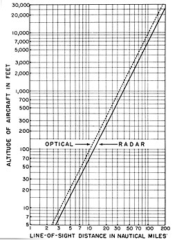
Figure 2-17.--Because radio waves are bent down slightly by the ionosphere their path is larger than the line-of-sight distance to the horizon. This graph illustrates the approximate line of sight and radar distances obtained at altitudes up to 30,000 feet.
2. Sea and ground return.--Although most of the ultra-high-frequency radio energy is consent rated by directive antennas into a narrow beam or lobe, some of this energy is projected downward from the aircraft where it strikes the land or sea below. Radar reflections from the land or sea directly below the aircraft return and show upon the scope screen as a diffused, irregular pattern close to the start of the trace. The area on the scope covered by such land or sea return depends largely on the altitude of the aircraft. At low altitudes, a small area is covered. Consequently, a small area about the start of the trace is covered by the returning echoes. At high altitudes, a correspondingly larger area of the scope is covered by the return because the stray radiation covers a larger area below the aircraft.
Land areas below the aircraft usually cause stronger, larger returns because the ground offers more and varied reflecting surfaces. Areas of sea below the aircraft return weaker, fewer returns because of the relatively flat surface intercepted by the stray radiations. In a rough sea, however, the advancing front of waves offers good reflecting surfaces and. in
--19--
addition to increasing the area of sea return on the scope, indicates generally the direction of the wind causing the high seas.
3. Target size, shape, and substance.--In general, large targets return echoes at greater ranges than small targets. A target that is broadside to the radar beam will return echoes from greater distances than a long but narrow target which is bow-on to the radar beam. The material of which the target is made has a decided effect upon the strength of the echo which it returns. Metal targets are detected at greater ranges than nonmetallic targets. A steel ship, for example, is detected at greater ranges than a wooden ship.
4. Fading.--Distant targets often fade in and out much like the fading of radio signals from a distant broadcasting station. Aircraft targets, in particular, usually fade rapidly on the radar scope, and reappear just as rapidly. One cause of this fading is the changing attitude of the reflecting surfaces of the target.
5. Nonstandard propagation of radio waves, trapping, ducts--a. General Features.--As a general rule, and in accordance with the accepted theory of wave propagation, it has been assumed that waves generated at frequencies above 30 megacycles travel from a transmitter outward along a long of sight and, with respect to radar, that targets in the line of sight will reflect a portion of these waves back to the source also along a line of sight. This has been and still remains the basic premise on which the explanation of the operation of radar is based. Reports on the variability of radar coverage show, however, that certain weather and atmospheric conditions prevailing along the transmission path may greatly modify the day-to-day and hour-to-hour normal radar range characteristics.
In order to establish a reference for the purpose of investigating the effect of atmosphere on radio wave propagation, a so-called standard atmosphere has been postulated. The standard atmosphere is likely to be found in nature when the air is well mixed so that no unusual temperature or humidity gradients can exist. A standard atmosphere may be defined as that condition of the atmosphere in which the temperature and moisture content of the air decreases uniformly with height.
In the standard atmosphere, the air temperature decreases with increasing altitude at the rate of 6.5° C. per kilometer from 15° C. at sea level. Although this condition is postulated as "standard," it is not necessarily normal at any particular location. The atmosphere is likely to be of standard composition when strong, gusty winds are blowing, because the turbulence created prevents both stratification of the air and establishment of nonstandard temperature and humidity gradients. Standard propagation is likely also when the water is colder than the air, or over land when cooling of the earth by radiation is limited by overcast skies. If rain is falling, the lower atmosphere in general will be saturated with water vapor, so that the existence of abnormal humidity gradients is prevented and propagation should be standard.
In the standard atmosphere both the air temperature and the moisture content decrease uniformly with height above the surface of the
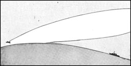
Figure 2-18.--A. Radar lobe pattern in standard atmosphere. Steady variation of temperature and humidity aloft. |
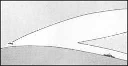
Figure 2-1 8.--B. Radar lobe pattern in nonstandard atmosphere. A duct has been formed on the surface and ship is detected. |
--20--
earth, so that the index of refraction of the atmosphere also decreases uniformly. However, the atmosphere is subject to many changes. The temperature may, for example, first increase with height and then begin to decrease. Such a situation is called a "temperature inversion." More important, the moisture content may decrease markedly with height just above the sea. This latter effect, which is called a "moisture lapse," either alone or in combination with a temperature inversion, may produce a great change in the index of refraction of the lowest few hundred feet of the atmosphere. The altered characteristics of the atmosphere may result in an excessive bending of the radar waves that are passing through the lower atmosphere. In certain regions, notably in warm climates, excessive bending is observed as high as 5,000 feet. The amount of bending in regions above this height is almost always that of normal atmosphere.
The atmosphere must be relatively calm in order to permit the existence of the conditions that produce this excessive bending. After a period of calm or of light breezes, the lower air may be stratified so that nonstandard propagation is likely throughout a wide area. There will be formed within this area a sort of duct or wave guide in which the radar waxes can be trapped. The most remarkable effect of such trapping is the extreme ranges that have been obtained as a result of it.
Numerous instances have been reported where the normal radar horizon range has been increased four or five times, while a few hours later, the same radar has failed entirely to detect targets clearly visible to the eye.
The duct in the atmosphere may be formed along the surface of the sea or elevated above the earth. In either case, the coverage of the radar will be changed by the great extension of detection range for targets within the duct. In figure 2-18, one possible type of deformation of a radar coverage pattern is illustrated. The duct acts very much like a wave guide that is used as the transmission line in the radar set. The humidity gradient is such that the rays from the radar antenna are bent an excessive amount, and they are trapped in a zone near the surface of the water. Since the effect of the duct is to guide the radiated energy around the curvature of the earth and back again to the antenna, the radar is able to detect the ship at a range much greater than normal.
If the moisture content of the air increases with height, the radar waves may be bent up instead of down. Nonstandard propagation of this sort reduces the radar coverage instead of increasing it.
b. Effect on radar performance.--The position of the radar antenna relative to the duct in the atmosphere is one of the most important factors in controlling the effect of trapping. The radar pulse can be trapped and carried out to very distant targets and back to the radar if the antenna lies within the duct. If the antenna lies below the duct, trapping may take place, but only if the radiated rays from the antenna enter at a very small angle. For this reason, elevated ducts that are very high will not have any direct effect on radar performance. On the other hand, if the antenna is a small distance above the top of the duct, blind zones may be present in the low-level portion of the coverage pattern that do not exist during standard propagation conditions. However, if the antenna is high above the top of the duct, as an airplane flying over a ground-based duct, no effect on the air-borne radar coverage will be apparent.
Since the ducts that are most important to the operation of shipboard radar are ground based, radars that have relatively low antenna heights are the most likely sets to experience trapping. Experiments and observations of shore radar installations in both the United States and England have indicated that low sites are rather generally affected by trapping while high sites experience the phenomenon relatively infrequently.
For some time after the discovery of trapping it was thought that the long ranges observed resulted from the diversion of a large amount of the radiated energy into the duct. Consequently, it was feared that the existence of trapping would cause a great decrease in coverage in the area above the duct. However, the conditions that exist in the most common type of trapping do not support this presumption. In spite of the great increase in ranges
--21--

Figure 2-19.--Variation of echo amplitude with constant radar performance.
in the duct, the amount of energy trapped is
small compared to the total energy radiated in
the pulse. The increased range apparently is
caused by the increased transmission efficiency
that exists with the duct.
In many cases, coverage will be reduced for
targets that are just above the duct. This reduction
is caused by the wave-guide action of
the trapping layer. The radiated pulse is contained
within the duct because the refractive
power of the atmosphere within this region is
such that the radiated rays are bent downward.
Directly above the duct there may then be little
or no energy, and targets flying there may not
be detected. However, energy may reach targets
that are well above the duct by traveling
along paths that enter the trapping region at
angles too great to be trapped.
The wavelength that can be trapped in the
duct formed by nonstandard propagation conditions
varies with the height of the duct. If
the duct is approximately 400 feet high, all
radar frequencies can be trapped within it.
However, if the duct is only 100 feet high, only
microwave energy will be affected. A duct
almost always exists within perhaps the first 20
feet above the water, but this is not yet of any
practical use since only K-band energy could
be trapped within such a narrow region. There
is fairly conclusive evidence of the rather general
existence of a surface duct 50 to 65 feet
high throughout the trade wind area of the
Pacific Ocean. This duct is capable of trapping
S-band and shorter wavelengths provided the
antenna lies within the duct. Because of the
characteristics of the ducts that are usually
formed, radar frequencies below approximately
250 megacycles are the least likely to be trapped.
The amount of refraction, that is, the amount
of angular deflection of the rays, is very small
and very rarely will exceed 1°. Such bending
does not affect radar operation except in regions
where the angle between the radiated ray and
the horizontal is very small.
Only low-angle search is affected by meteorological
conditions; performance of the radar
is rarely affected by weather for targets above
approximately 1° position angle.
A very serious operational consequence of
trapping is the misleading of radar operators
as to the over-all performance of the equipment.
Long-range echoes caused by trapping have frequently
been assumed to indicate good condition
of the equipment when precisely the
--22--
opposite may be the case. For example, figure 2-19 shows a part of a record of echo amplitude taken during an investigation of radar propagation. The performance of the radar was maintained at a constant level by the use of an echo box. The target was 30 miles away from the radar, with the path of the pulses passing over sea. Aside from the rise and fall of the tide, the variations in echo strength are due to changing characteristics of the targets or of the propagation pathway. The tremendous variation shown in figure 2-19 would certainly preclude the use of this target as a standard to check the performance level of a radar. At one point in the curve, the echo changed two-hundred-thousand-fold (53db) within 2½ hours. However, the phenomenon of trapping does not invalidate the measurement of echo height on nearby targets its a criterion of overall set performance, since the echoes from objects well within the optical horizon are not affected appreciably by propagation variations.
Under conditions where the security of radar transmissions is involved, the possibility of trapping should be constantly kept in mind. When a duct is present, the enemy can intercept both radar pulses and VHF communications at far greater ranges than normal. When trapping is known to be present, and a choice of frequencies is available, it may be better to choose the lowest band since the high frequencies are the more likely to be trapped. Tints, decisions as to when to employ radar silence must be modified by consideration of propagation conditions.
Trapping may be the cause of apparently inexplicable failure in communications. Elevated ducts do not have much effect on ship-to-ship or ground-to-ship communications unless the duct is at low level. However, a plane flying within an elevated duct may have difficulty communicating with a plane outside the duct or with a distant ship because the duct may act as a barrier. When the temperature inversion and moisture lapse are very steep over a relatively thin layer of the atmosphere, radio waves may be reflected directly from the bottom of the duct. Under this condition, which probably will be encountered only rarely, the lower frequency radar and communications waves ma}' be reflected repeatedly between the duct and the sea, and so carried long distances, even without trapping taking place. There will be skip distances associated with this type of propagation because the nature of the reflection is such that the waves are returned to earth only at intervals. If a plane is flying above a thin, sharply bounded duct of this type, it may be impossible for communications to be established between the plane and the ship. In rare cases, a phenomenon of this sort may also be responsible for failure of IFF. When communications from a plane fail, or the plane cannot make contact on a navigational aid, the pilot may be able to reestablish contact by changing altitude to get either above or below the duct.
When trapping causes echoes to be returned from targets at long ranges, the pips are likely to fluctuate far more than those from targets at short range. This fading is caused by changing propagation conditions within the duct. Such fading is of large amplitude, perhaps involving a change in echo power of as much as one-thousand-fold, and the echoes vary over a period of approximately 15 minutes. Violent fading of echoes appears to be a characteristic feature of trapping conditions that may aid the operator in realizing when such conditions exist.
If the water vapor content of the air increases with elevation, the radar waves are bent up instead of down. This condition, which is referred to as substandard, can exist in some kinds of fog or when fog is about to form. Although not enough is yet known about radar propagation in fogs to state its full effect, it appears likely that nearly all fogs produce substandard conditions. The obvious danger of this condition is that the fog prevents ordinary optical search, and at the same time reduces the radar detection range on surface vessels and low-flying aircraft. Unfortunately, there is very little that the operator can do to combat the effect of fog except to run his set at the greatest possible sensitivity.
Airplanes often fly very low to avoid detection by radar. However if a duct is formed near the surface of the water, such evasive action will probably be unsuccessful. If the
--23--
presence and height of the duct were known, better protection against radar detection would be furnished if the planes were to fly just above the top of the duct.
The changing propagation conditions that radar waves can encounter, then, can have considerable effect on radar performance. To summarize, the effect of trapping on a radar may be to:
Increase the range of detection for airplanes flying within a duct.
Reduce the range of detection for airplanes flying just above a duct.
Reduce the range of detection for low-flying planes in some types of foggy weather.
Modify the height at which airplanes should fly to avoid detection by enemy radar.
Cause errors in height finding for targets below position angles of 1°.
Increase the extent of clutter from sea return, and thus reduce the operational efficiency.
Increase the range at which a navigational aid can be effective.
Increase the range at which radar signals can be heard.
Modify the degree of jamming either suffered or inflicted.
Weather effects cannot be blamed indiscriminately for variable performance of radar. In general, inadequate adjustment or incipient electrical failure will cause a far greater decrease in range than any variation in the propagation conditions. For example, failure to detect a high-flying airplane at short range cannot be attributed to nonstandard propagation; trapping affects the detection of targets only at low angles above the horizon.
c. Meteorological factors that came trapping.--The atmospheric conditions which allow standard propagation to take place are common. The peculiar structure of the atmosphere that produces trapping, especially for frequencies of 3,000 megacycles and higher, also occurs fairly often in many parts of the world. Several types of meteorological conditions can produce the temperature and humidity gradients necessary for trapping to take place.
Warm continental air blowing over a cooler sea leads to the formation of a duct by causing a temperature inversion as well as by evaporation of water from the cooler sea into the lower levels of the warm dry air. The base of such a duct is usually the sea surface with the trapping region extending several hundred feet upward. At higher latitudes--above 25° or 30°--this type of trapping is most prevalent along the eastern shores of continents. If it is present in the lower latitudes, the duct will be formed on the western coasts. This distribution with latitude results from the normal direction of the wind, which must be off-shore to produce the effect. Ducts of this sort will form only when there is a distinct temperature difference between the sea and the air blowing from the land. Hence, conditions are most favorable for trapping in the summer months. The duct is usually from 500 to 600 feet high, and it tends to remain level for a distance of 100 to 200 miles out to sea. Near the coast, trapping will be found to be strongest just after noon, and weakest just before dawn. Fog usually is not associated with the meteorological conditions that produce this form of trapping, but at times a surface fog will be observed 5 to 10 miles off shore.
Over the open ocean, a surface duct such as that in A or B, figure 2-20, may be formed by cool air blowing over a warmer sea. There is no temperature inversion associated with this phenomenon, and the entire effect is caused, apparently, by the evaporation of water into the lower levels of the atmosphere. Ducts of this sort are often created by easterly winds, such as the trade winds, that have blown for a long distance over the open sea. The height of the duct increases with the wind speed, and at the higher wind speeds typical of Pacific trade belt--10 to 20 knots--ducts 50 to 60 feet high occur quite generally. These ducts seldom attain the height and intensity necessary to entrap the lower frequencies, but S- and X-band radars that have antennas within the duct show better range performance for the detection of surface vessels and low-flying aircraft than can be predicted from consideration of the characteristics of the radar alone. These ducts are important because they extend for long distances.
An elevated duct as in C or D, figure 2-20, may form in an area of high barometric pressure
--24--
because of the sinking and lateral spreading of the air, which is termed "subsidence." When the air is warm and dry and the subsidence takes place over the sea, water is evaporated into the air, forming a moisture gradient that leads to the formation of a duct. Such ducts are always formed above the sea, with the base of the trapping layer ranging in elevation from a few thousand to 20,000 feet. Subsidence trapping can nearly always be found in the tropics; the ducts so produced usually are low and strong off the western coasts of continents in the trade winds latitudes, and high and weak near the equator. In areas where a monsoonal climate is found, subsidence trapping is weak or nonexistent in the moist, onshore, summer monsoon, and (he duct is low and trapping strong during the dry, off-shore, winter monsoon. When a duct is formed as the result of subsidence, the strength of the trapping varies throughout the day, being weak in the mid forenoon, and strong after sunset.
Other meteorological conditions that may produce trapping are cooling of hind at night by radiation and the mixing of two masses of air, as at a warm or cold front. The ducts formed by these effects are likely to be of such limited extent that they are unable to modify radar propagation by any appreciable amount.
d. Prediction of non-Standard propagation.--In spite of the fad that the relation of weather to the production of trapping conditions is not fully understood, enough is known to permit a meteorologist to make a fairly reliable predict ion. Considerable equipment is required to measure the several variables that must be known to determine the structure of the atmosphere, and rather specialized meteorological skills are needed to interpret the data. Since neither the skills, nor the equipment is generally mailable to the fleet, reliable predictions are diffcult to make on board ship. However, even in i hi' absence of specialized equipment and personnel, it may sometimes be possible to predict the formation of ducts from observation of weather conditions, coupled with simple measurements that can be made on board any ship. Such ail estimate cannot hope to be highly reliable at present, but continuing research on the problem may ultimately reveal a fairly simple relationship between weather and trapping that will allow propagation conditions to be evaluated routinely.
For a number of reasons the meteorological conditions in a region of high barometric pressure are favorable for the formation of ducts. Among the favorable factors are: subsidence, which creates temperature inversions, and which occurs in areas where the air is very dry so that evaporation can take place from the surface of the sea; calm conditions that prevent mixing
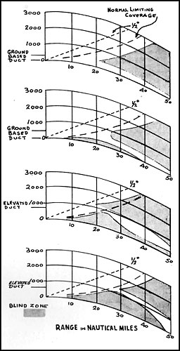
Figure 2-20.--Coverage diagram showing the existence of ground-based and elevated ducts.
--25--
of the lower layers of the atmosphere by turbulence, allowing thermal stratification to persist; and clear skies which permit nocturnal cooling over land.
The conditions in a barometric low, on the other hand, generally favor standard propagation. A lifting of the air, the opposite of subsidence, usually occurs in such regions and it is accompanied by strong winds. The combined effect of these factors is to destroy any local stratification of the atmosphere by a thorough mixing of the air. Moreover, the sky is usually overcast in a low-pressure area, and nocturnal cooling is therefore negligible. Very often rain falls in a low-pressure area, and the falling drops of water have the effect of destroying any nonstandard humidity or temperature gradients that may have been established.
In all of the weather conditions that produce trapping, the atmosphere must be sufficiently stable to allow the necessary stratification of the atmosphere to be established and to persist. Thus, continued calm weather or moderate breezes are necessary. It must be emphasized, however, that even if weather conditions may favor the formation of ducts, they do not always produce them.
In terms of the readily observable phenomena, the weather conditions that may favor trapping are:
A moderate breeze that is warmer than the water, blowing from a continental land mass.
Clear skies, little wind, and high barometric pressure.
A cool breeze blowing over the open ocean far from large land masses, especially in the tropical trade wind belt.
Smoke, haze, or dust that fails to rise, but spreads out horizontally, indicating quiet air in which a temperature inversion may exist.
When the air temperature at bridge level on a ship definitely exceeds that of the sea, or when the moisture content of the air at bridge level is considerably less than that just above the water, and the air is relatively calm.
Although trapping conditions can occur at any place in the word, the climate and weather in some areas make their occurrence more likely. In some parts of the world, particularly those possessing a monsoonal type of climate, variation in the degree of trapping is mainly seasonal, and enormous fluctuations from day to day may not occur. In other parts of the world, especially those in which low barometric pressure areas recur often, the extent of nonstandard propagation conditions varies considerably from day to day, even during the season of greatest prevalence.
Even though the geographical and seasonal aspects of trapping are not yet so firmly established that a map of the world can be drawn with trapping areas reliably delineated, it is possible to make a general summary.
(1) Atlantic coast of the United States.-- Along the northern part of this coast, trapping is common in summer, while in the Florida region the seasonal trend is the reverse, with a maximum in the winter season.
(2) Western Europe.--On the eastern side of the Atlantic, around the British Isles and in the North Sea, there is a pronounced maximum of trapping conditions in the summer months.
(3) Mediterranean region.--Available reports indicate that the seasonal variation is very marked, with trapping more or less the rule in summer, while conditions arc approximately standard in winter. Trapping in the central Mediterranean area is caused by flow of warm dry air from the south (sirocco) which moves across the sea and thus provides an excellent opportunity for the formation of ducts. In the wintertime, however, the climate in the central Mediterranean is more or less a reflection of Atlantic conditions and hence it is not favorable for duct formation.
(4) The Arabian Sea.--The dominating meteorological factor in this region is the southwest monsoon that blows from early June to mid-September and covers the whole Arabian Sea with moist equatorial air up to considerable heights. When this meteorological situation is fully developed, no occurrence of trapping is to be expected. During the dry season, on the other hand, conditions are very different. Trapping is then the rule rather than the exception, and on some occasions extremely long
--26--
ranges, up to 1,500 miles, have been observed on P-band radar on fixed echoes.
When the southwest monsoon sets in early in June, trapping disappears on the Indian side of the Arabian Sea. However, along the western coasts, conditions favoring trapping may still linger. The Strait of Hormuz is particularly interesting as the monsoon there has to contend against the shamal from the north. The strait itself lies at the boundary between the two wind systems, and a front is formed with the warm, dry shamal on top and the colder, humid monsoon underneath. As a consequence, conditions are favorable to the formation of an extensive duct which is of great importance to radar operation in the Strait of Hormuz.
(5) The Bay of Bengal.--The seasonal trend of trapping conditions is the same as in the Arabian Sea, with standard conditions occurring during the summer southwest monsoon, while trapping is found during the dry season.
(6) The Pacific Ocean.--This region appears to be one where, up to the present, least precise knowledge is available. However, there seems to he definite evidence of the frequent occurrence of 1 rapping around Guadalcanal, tIn- east coast of Australia, and around New Guinea. Observations along the Pacific coast of the United States indicate frequent occurrence of trapping, hut no clear indication of its seasonal trend is available. The meteorological conditions in the Yellow Sea and the Sea of Japan, including the island of Honshu, are approximately like those of the northeastern coast of the United States. Therefore, trapping in this area should be common in the summer. Conditions in the South China Sea approximate those off the southeastern coast of the United States only during the winter months, when trapping can be expected. During the rest of the year, the Asiatic monsoon modifies the climate in this area and no data are available as to the prevalence of trapping during this time. The trade winds in the Pacific lead to the formation of rather low ducts quite generally over the open ocean.
6. Weather.--Since moisture has substance, and hence reflects radio-frequency energy, the radio-frequency pulses of a radar beam are capable of detecting the presence of rain, or dense, electrically charged clouds. The image as presented on a scope appears as a strongly illuminated area of irregular shape.
The intensity of cloud echoes as indicated by a radar set depends upon:
The total amount of visible water per unit volume of the atmosphere.
The size of the water droplets.
The frequency of the radar set.
a. General.-- (1) The relationship of the intensity of a cloud echo to the intensity or development of the meteorological condition is at present known only qualitatively.
(2) When cloud formation is used simultaneously with the current synoptic information
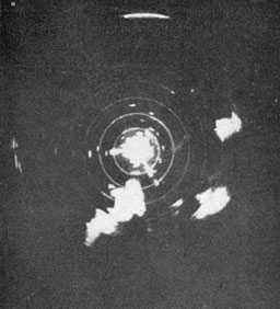
Figure 2-21.--Radar echo from thunderstorm of the convective type shown on the PPI. Radar is adjusted for 40-mile range and concentric lines are 5-mile markers. Irregular bright area at azimuth 190 and 20-mile range is thunderstorm. Note bright, solid appearance of echo and distinct boundary. Thunderstorms may often be identified as such by tipping parabola upward and scanning in elevation to disclose vertical structure of area from which echo is coming. This is readily computed from range and elevation angle data. In this case scanning in elevation disclosed a vertical extent of this storm of 40,000 feet, probably exaggerated to some extent by the beam width. Summer thunderstorms, however, give radar echoes to great heights in the atmosphere, thus readily distinguishing them from echoes from cumulus congestus clouds and other phenomena.
--27--
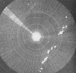
Figure 2-22.--PPI presentation of radar echoes from cold-front thunderstorms. Radar is adjusted to 100-mile range. Range markers are at 20-mile intervals; 80-mile marker is farthest visible. Cold-front thunderstorms appear as line of bright echoes in northwest quadrant. Note ready distinction from irregular distribution of convective type of thunderstorm shown in figure 2-21. Radar was located at Cambridge, Mass., and photo was taken July 22, 1943, at 5 p. m. Because storm echoes may be seen so much farther than normal land targets (due to their great vertical development) it is important to search from time to time with the long-range adjustment of the system in order to pick up the echo at the earliest possible moment.
of the same area, an estimate may be made of the conditions aloft. For tactical purposes, aircraft may be directed to avoid weather conditions hazardous to flight operations within the range of the set. In many cases a check is available on the development of storm conditions.
b. Identification of thunderstorms.-- (1) The echo of a thunderstorm is one of the most easily identified signals detected. When examined on the PPI, it appears as a bright, dense, central area with indistinct boundaries. Because of the vertical extent of thunderstorms, the cloud echo will be indicated at higher elevation angles than targets at the same range. The maximum angle of elevation at which the cloud echo is received and the distance is a rough measure of the height or vertical structure of the thunderstorm.
(2) Air mass or convective thunderstorms are scattered in a random manner; the area covered by an individual thunderstorm is usually of the order of several square miles. This type storm moves with the velocity and direction of the general circulation.
(3) Orographic thunderstorms are generally characteristic of the terrain for certain atmospheric conditions. This type of thunderstorm will usually show little movement.
(4) Cold-front thunderstorms are usually arranged in a line and bear a marked resemblance to the frontal system. Warm-front thunderstorms may be scattered or they may form along a line.
c. Identification of frontal conditions.--(1) General.--Frontal conditions are generally accompanied by thunderstorms, rain showers, rain, and various cloud systems. The greatest concentration of activity is usually located in the frontal zone.
(2) Cold fronts.--An active cold front is easily located as a line of cloud echoes. The structure and activity of cold fronts can be estimated qualitatively by consideration of the intensity of the cloud echoes, spacing between areas of brightness, the area covered by each cloud, the vertical extent and the velocity of the front. Weak cold fronts are often poorly defined and may be missed entirely.
(3) Warm fronts.--Echoes from warm fronts are extremely variable. Atmospheric conditions (thunderstorms, showers, general precipitation, etc.) associated with warm fronts usually cover a wide area. Occasionally these conditions are concentrated in the active frontal zone; however, the majority of cloud echoes from warm-frontal conditions will be hazy and will cover extensive areas of the order of hundreds of square miles.
(4) Equatorial front.--Echoes reported from the equatorial front may have the characteristics of cold fronts or warm fronts or a combination of both.
d. Identification of other atmospheric echoes--(1) Line squalls.--The cloud echo of a line squall will appear as a long, narrow, rapidly moving thunderstorm (fig. 2-23).
(2) Showers.--Echoes received from showers are generally less intense than thounderstorm echoes and have a hazy structure. The central portion is not always of the greatest intensity.
--28--
Cloud echoes have been reported when no precipitation was reaching the ground in the area of the cloud echoes. It is still uncertain as to the reasons why cloud echoes received from certain atmospheric conditions are not received again under an apparently similar set of atmospheric conditions at another time.
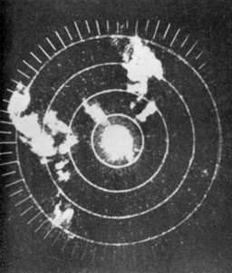
Figure 2-23.--Radar echo from precipitation in cumulus con-gestus clouds. System is adjusted for 20-mile range and markers show 4-mile intervals. It is noted that appearance on PPI is similar to thunderstorm echo. Distinction is made by scanning elevation. In this case it was disclosed that vertical development extended to only 15,000 feet. The meteorologist can thus get a valuable hint as to lapse rate aloft and vertical extent of instability by scanning in cross section through cloud areas. While no precipitation may reach the ground in some of these cases the area would undoubtedly be a poor one to fly through with aircraft. Few land targets are seen on the scope because the beam is elevated above the horizon.
B. CONSTANT FACTORS. Regardless of the type of radar, there are certain "constant" factors which limit performance or impair to some extent the correct interpretation of screen patterns:
1. Power.--Power output from airplane generators, limitations of space, and the weight that can be carried by different types of aircraft affect the radiation power of air-borne radar and, in consequence, determine to a large extent the maximum ranges which can be attained.
2. Beam width versus trace width.--The width of the radar beam varies from about one-half of one degree in some equipments to as much as 30 degrees in others. The time trace on the map-type radars is a fine sweep line which denotes the orientation of the antenna in azimuth with respect to dead ahead. Also, it represents a center line through the radar beam. However, echoes from any target lying within the beam width of the radar will register on the time trace. Thus, if a beam is, for example, 10° wide, the leading edge of the 10° beam will cause an intensification 5° too soon on the rotating time trace; likewise, the trailing edge of the beam will cause retention of the intensification 5° too long. See figure 2-24. The result is an elongated indication on the scope, giving the impression that the target is of greater length than is actually the case. This effect varies with range.
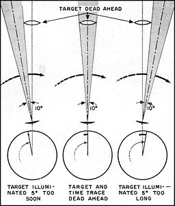
Figure 2-24.--The size of the target on the scope is no reliable indication of relative target size.
This diagram shows how the beam width tends to distort target size (length).
3. Range resolution and diffusion of light.--Depending on the angle at which a radar beam strikes a target, the apparent size of an object
--29--
on map-type presentations is increased by a diffused fringe of light which surrounds the scope presentation of all targets. On the 20-mile scale, this extra illumination will cause an error of about one-tenth nautical mile. The cumulative effect of these errors results in a slight apparent increase in the dimensions of land and other targets, and thus partially obscures certain identifying characteristics of size, shape and depth. In some cases, this diffusion is sufficient to mask or fill in scope images of channels and rivers. The condition, however, can be cleared up considerably by the intelligent manipulation of the tilt control of the antenna spinner.
None of the above factors seriously affects the accurate computation of range and does not attain major importance unless the radar is to be used to bomb cities and islands where sharp definition is necessary for the selection of the proper targets. Greater definition has been attained in.the newer equipments by the use of a narrow beam width, a short pulse length, and operation within the microwave frequencies.
4. Maintenance.--Probably the most important factor which limits the ability of any piece of electronic gear to function at top efficiency is the level of systematic maintenance which the system receives. The regularity with which preflight and other periodic performance checks are made will do much to insure that not only are the maximum number of available airborne electronic installations functioning but that each one is operating at a degree of efficiency which will allow tactical commanders to expect the maximum in performance.
--30--
[BLANK PAGE]
--31--
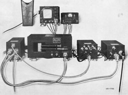
ASB
--32--
EQUIPMENTS
ASB SERIES
NOTE:-These equipments were designed and manufactured prior to the adoption of the "AN" nomenclature system and continue to bear the older, Navy ASB designation. ASB-1, -2, -3, -4, and Bendix receivers for ASB-5 (Serials 1 through 207) are obsolete.
It is expected that ASB installations ultimately will be replaced by AN/APS-4.
I. FUNCTION
A. PRIMARY PURPOSE. ASB is low-powered type of L-band air-borne radar intended primarily for search use.
B. SECONDARY USES. Although designed specifically to operate as a search radar, ASB through its long period of use has lent itself admirably to such applications as navigation, beacon homing, low-altitude bombing, and IFF (target identification).
II. DESCRIPTION
A. MAIN COMPONENTS. The units comprising the ASB system are:
-
Movable, directive antennas.
-
Hydraulic antenna controls.
-
Low-powered transmitter.
-
Receiver.
-
Antenna switching system.
-
Indicator.
-
Control unit.
-
Power supply, cables, junction boxes.
Two Yagi, or "fishbone," antennas are provided, usually mounted under the port and starboard board wing tips (see fig. 2-25), or on the port and starboard sides of the hull. At the operator's position arc located the hydraulic antenna controls, the receiver, indicator, and the control box units. Generally, all other units are situated in a remote location in the aircraft since they require no continuous manipulation or adjustment during operation.
B. ANTENNA SCAN AND SCOPE PRESENTATION. 1. Beam coverage and antenna control.--Each of the antennas emits radio energy in a beam or lobe approximately 40° wide in the horizontal plane. In the vertical plane the beam is approximately 45° in depth when the antennas are in the homing position and about half that depth when in the search position.
By means of separate hydraulic controls, one for each antenna, the antennas can be moved together or independently, from ahead outboard through an arc of about 90° (see fig. 2-26). A notched arrangement of the control mechanism allows the antennas to be moved through their train in 8° steps.
When the hydraulic controls are fully retarded, the antennas point outboard to port and starboard, at right angles to the line of flight (search position). When moved to their full forward position the antennas point dead ahead (homing position). Intermediate positions of the antennas may be judged by observing the positions of the antenna control handles.
2. L-scan.--The scope in the ASB indicator is the L-type (see fig. 2-27), where range is indicated by the position of blips upward from the bottom of the vertical time trace. Bearing is

Figure 2-25.--The ASB antennas are mounted under the wing tips on the TBF aircraft.
--33--
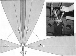
Figure 2-26.--Manually operated hydraulic controls permit the wing tip antennas to be rotated in steps
from the homing position dead ahead, outboard to the search position.
The antennas may be moved singly or together.
indicated by the lateral disposition of the blips about the trace.
The width of the beam is such that in the full forward position an overlap of both antenna beams is produced; from targets dead ahead, then, each antenna receives an equal amount of reflected energy and so produces a blip equally spaced laterally on the trace. Targets slightly off to either side of dead ahead will produce a blip whose sides are of unequal length and so indicates their bearing. Echoes from port or starboard targets are indicated on the scope as blips on the port or starboard sides of the trace only when one or the other of the antennas has been moved sufficiently to place its beam on the target.
A single target such as a ship, aircraft, or buoy will produce a single blip on the trace, its
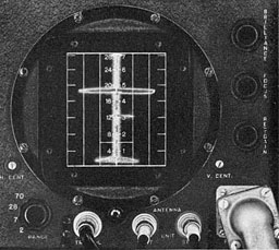
Figure 2-27.--When the "gain" or sensitivity of the receiver is increased, electrical and atmospheric noise causes an irregular indication (grass) along the length of the trace. A large target is indicated at about 4% miles and a small target to starboard at 3 miles. The height of Ihe lower edge of the sea return furnishes a rough indication of the aircraft's altitude.
--34--
lateral length affording some indication of its relative size. Land targets, ship convoys, or closely grouped islands, because they return many echoes, produce many blips closely bunched together.
Stray radiation of radio energy from the antennas to the sea or terrain directly below the aircraft returns echoes of considerable strength. They appear on the scope screen as irregular blips near the bottom of the trace. This irregular scope pattern is called the sea return (or ground return). The distance upward from the bottom of the trace to the bottom of the sea return is a measure of the aircraft's absolute all it ude.
3. Range settings.--Four operating ranges are provided-2, 7, 28, and 70 nautical miles. A graduated plastic scale placed over the face of the scope enables the operator to judge target ranges with a fair degree of accuracy for the 7-, 28-, and 70-mile ranges. On the 2-mile setting, ranges must be approximated.
C. IMPROVEMENTS INCORPORATED IN LATER ASG EQUIPMENTS. Long standard for carrier-based aircraft, the ASH radar was continued in use for some aircraft types because of a series of improvements which enabled it to meet the demands of the fleet. Greater security, longer ranges, increased accuracy, and ability to cany nut varied tactical assignments were made possible with the later ASB equipments.
1. Frequency changes.--Because of ASB's comparatively low frequency, enemy jamming attempts have been feared more with ASB than Willi more modern microwave equipments. To assist in avoiding such action by the enemy, improved transmitters have been designed to operate nt any of three different frequencies instead of only one as was formerly the case. This group of three frequencies are referred to as "A1," "A2," and "A3." A change from one frequency to another cannot be made in flight, chiefly because antenna adjustments are necessary; however, a change between flights is easily accomplished and different aircraft in a squadron may operate on different frequencies.
2. Main components.--The ASB radars equipped for "A"-band operation include two new units: The ASB-7A indicator, which is a complete redesign, and the ASB-7A (or ASB-7B) transmitter. The ASB-7A transmitter is simply the ASB-7 transmitter modified to be tuneable over the "A" band. The ASB-7B transmitter is the redesigned, high-power, plate-pulsed unit. In addition, the complete radar set includes the ASB-7 or ASB-Series receiver of the type already in use, which is capable of being tuned to any of the "A" band frequencies, the ASB-7 control unit, rectifier power unit and antenna switching unit.
3. Sensitivity switch.--In addition to "A"-band operation, a second safeguard against enemy jamming is the sensitivity switch, mentioned above, for the receiver. The switch is designed to prevent saturation of the receiver by jamming signals.
4. Special features and advantages of the new ASB.--Installations using the new ASB-7B transmitter and the ASB-7A indicator have, in addition to greater security, several other advantages. The ASB-7B transmitter more than doubles the power output of the ASB-7 or ASB-7A transmitter-approximately 8 to 10 kilowatts (peak power) as compared to 3 to .'i kilowatts. This power increase accounts for:'i(i to l() percent increase in range results. Also, the ASH 7H transmitter has been designed to
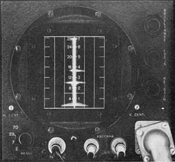
Figure 2-28.--On the 28-mile range two single-ship targets appear--one at 1 5 miles, the other at about 1 1 miles. With the antennas in the homing position the near target is almost dead ahead while the farther one is slightly off to the starboard side of dead ahead.
--35--
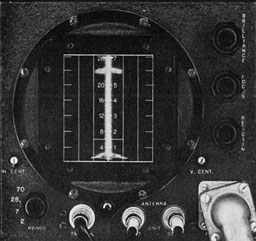
Figure 2-29.--A beam-on approach to ships in convoy might produce the blip shown above.
If shows several target blips closely grouped at about 24 miles.
give low "case radiation" so that interference affecting radio reception is reduced.
Still other advantages in performance, operation and maintenance are provided by the new ASB-7A indicator. Among them are:
(a) More accurate indication of target ranges.
(b) New range scales fitting the ASB for the tactical demands of present-day carrier-based aircraft; a 150-mile range with 30-mile calibration intervals; a 50-mile range with 10-mile calibration intervals; a 15-mile range with 3-mile calibration intervals; a 5,000-yard range with 1,000-yard calibration intervals, and additional 200-yard intervals between zero and 2,000 yards (provided for torpedo runs and bombing).
(c) Provisions for operating ASB with AN A PA 16 (low altitude bombing equipment).
(d) Circuits which maintain substantially optimum focus and stable operation on all ranges.
(e) Addition of front-panel controls to compensate for effects of generator voltage and wave-form variations.
(f) Triggering from leading edge of pulse, eliminating the "inherent error" of former indicators.
III. TACTICAL EMPLOYMENT
A. SEARCH. 1. Types of targets.--In the PPI-type (and to some extent, the B-type) scope presentations, targets are displayed in their true azimuth and range relation to the searching aircraft. Coastal areas, islands, harbors, rivers and large lakes are shown in maplike form. But in equipments such as the ASB which employ the L-type scope presentation, all targets are represented by blips-or the absence of blips. Beading the L-type scope pattern requires the mental facility of converting blips of all shapes and sizes and numbers into a mind picture of the types of target they represent.
With the exception of the sea return caused by the return of echoes from the sea directly below the plane, sea areas generally return no echoes. So, when flying over water areas there is an absence of blips on the trace. (The exception to this is when a relatively rough sea surface causes waves high enough to return echoes.)
Conversely, land masses return many echoes, their strength and number varying with relation to the topography of the terrain, the range at which they are received, and the sensitivity (or "gain" setting) of the receiver. The depth of a land mass can be ascertained by the amount of trace covered by the blips.
Single ship targets, figure 2-28, produce single blips, but their size and depth on the trace cannot be relied upon to indicate the relative
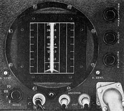
Figure 2-30.--On the 7-mile range an aircraft target lies dead ahead at about 3½ miles.
--36--
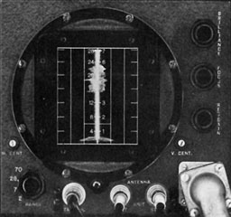
Figure 2-31.--This irregular long blip is caused by reflections from an island dead ahead.
size of the target, for the area and composition of the reflecting surface offered by the target to the beamed energy determines the strength and size of the blip. A small ship broadside may produce a blip as large and as strong as a large ship bow-on.
Ship convoys, figure 2-29, produce many blips in a small area on the trace but each ship blip is usually individually distinct because of the sea area separting the ships. Small islands and projecting strips of land, however, return one large blip (consisting of many small blips) having a jagged and irregular outline.
Single aircraft target blips, figure 2-30, have the same general characteristics as a single ship blip excepting that, because of the changing attitude presented by an aircraft in flight, its blip will "beat" or pulsate. Aircraft blips can he recognized by their relatively faster movement up or down the trace, or their complete lack of movement. An aircraft on a reciprocal course to the search aircraft will produce a blip which moves down the trace rapidly. The range to an aircraft on the same course, ahead, will be closed less rapidly than for a ship target. If the speed of the two aircraft is identical, the target blip will remain in one position for a long period of time.
2. Wind (or drift) pattern.--High surface winds cause otherwise calm seas to become rough, resulting in an increase in the reflecting area of the sea surface in certain directions and causing an increase in the sea return. In general, the sea return rises highest on the trace when the antenna is pointing toward the wind and is less when the antenna is pointing downwind. Winds of 15 knots or better can be checked in this manner, from altitudes of 1,500 feet and below.
3. Altitude ranges.--ASB is not designed for high-altitude operation, works less efficiently above 10,000 feet, and is subject to electrical breakdown at higher altitudes. The best altitudes for search with ASB are approximately 6.000 feet and below.
The table below presents a general performance indication of the equipment for various kinds of targets.
| Type of Target: |
Average detection
range (miles)
(1,800 feet altitude) |
| |
Mountainous terrain |
50-60 |
| |
Coastal rolling hills |
35-45 |
| |
Small, flat islands |
15-20 |
| |
Task force, convoy |
35-50 |
| |
Single capital ship |
25-35 |
| |
Vessel, 10,000 tons |
20-25 |
| |
DE, PC boat |
10-15 |
| |
Wooden escort vessel |
7-10 |
| |
Submarine, surfaced or with conning tower awash |
5-10 |
| |
Aircraft |
4-5 |
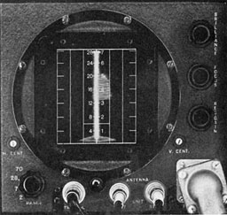
Figure 2-32.--With the starboard antenna pointed 90° to starboard an island blip appears at about 13 miles.
The height of the blip on the trace generally denotes the depth of the island.
--37--
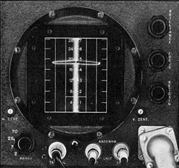
Figure 2-33.--With the ASB receiver tuned to the YJ beacon frequency a strong coded beacon signal shows at about 1 8 miles.
B. NAVIGATION. Radar navigation with ASB means, primarily, identifying with respect to range and azimuth position the characteristic blips of coast lines, strings of islands, harbors or other recognizable terrain contour features and comparing this information with charts of the area for the purpose of making landfalls, guiding a flight through channels, returning to a base or homing on a specific target.
1. Homing: Radar targets.--Movements of the antennas for search purposes through their 90° arc makes it possible to pick up coast-line promontories, harbors or islands (see figs. 2-31 and 2-32). After a target has been identified by reference to its known geographical, charted location, the aircraft's heading is altered to home on it and the antennas are swung to the dead-ahead, or homing, position.
Drift can be approximated to a fairly accurate degree by observing the direction of the antenna when a high sea return on one side of the trace is produced (See "Wind (or Drift) Pattern," p. 37). Actual ground speed can be estimated by observing over a measured period of time the movement of the target blip down the trace. Knowing these factors, a collision course can be developed for homing on the selected target.
2. Homing: Beacon targets.--Radar beacon homing, although requiring that all of the factors as in the case of target homing be known, is made easier of accomplishment for the following reasons:
(a) Greater homing accuracy results because, instead of homing on an indefinite and sometimes only generally identifiable radar target, the radar receiver, tuned to a radar beacon frequency, receives a coded, definitely identifiable signal from a beacon transmitter whose actual location is a matter of previous knowledge.
(b) Instead of being a weak, reflected radar echo, the radar beacon signal is a relatively powerful transmitted signal and can be observed at much greater ranges.
(c) Retiming a radar receiver to a radar beacon transmitter frequency clears the scope screen of echo blips. Thus, radar beacon signals, if the beacon is within range, appear sharply and distinctly on the scope screen, correct in range, and, when the antennas are in the forward or homing position, correct in relative hearing. (See figs. 2-33 and 2-34.)
Identity of radar beacon stations is established by observing the coded sequence of the signal blips as they appear on the scope screen.
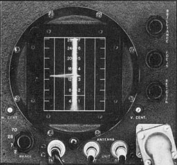
Figure 2-34.--Same target as in figure 2-33. Range is closed slightly. The displacement of the blip toward the left of the trace indicates that the search aircraft has changed bearing slightly to starboard.
--38--
C. BOMBING OR TORPEDO DROPPING. 1. Factors to be determined.--Bombing with ASB presupposes that a definite target has been selected and homed on and that the range has been closed sufficiently to permit use of the 2-mile range scale. As explained previously for the homing techniques, drift and speed must be determined and taken into account when making a bombing run.
In making a bombing run, observation of the target blip's lateral position on the trace can be improved immeasurably if as the range is closed the two antennas are moved simultaneously a few notches outboard from the homing or full forward position. This procedure narrows t lie overlap area of the two antenna lobes ahead of (be aircraft. Then, even a slight deviation of tlie aircraft from the true homing course will be apparent from the rapid movement of the blip either side of t be trace.
2. Release point.--In general, the greater the altitude, the more difficult it is to home directly over it target. Therefore, in order to reach the release point, bombing with ASH calls for low-altitude homing on a specified target with a high degree of accuracy right down to the last few hundred yards.
The bomb release point is determined from a reference point called the "mergence point" which on the ASB indicator is a noticeable change in the appearance of the target blip at a range of about 500 yards. The actual release point may be at the mergence of the target echo with the top of the sea return or it may be at a point obtained by a timing count from its first appearance.
On the 2-mile scale, certain features of sea return display must be kept in mind when determining the release point:
- Sea return is a function of the aircraft's altitude.
-
Sea return tends to mask the blip of a target at close range.
Therefore, the sensitivity or "gain" of the receiver must be reduced in order to keep the sea return at a minimum (and to prevent the target blip, at close range, from reaching the saturation point).
--39--
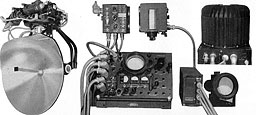
AN/APS-15
--40--
AN/APS-15
I. FUNCTION
A. PRIMARY PURPOSE. AN/APS-15 is an X-band radar designed primarily for general search operations in heavy patrol craft.
B. SECONDARY USES. AN/APS-15 may be employed for navigation, beacon homing, and pattern bombing. In conjunction with other electronic equipment, it may be used for target identification.
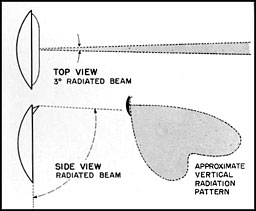
Figure 2-35.--Looking down from the top the beam emitted from the antenna spinner is 3° wide. Viewed in a vertical plane, the radiation pattern of the beam, unlike in other types of PPI equipment, is made purposely wide to cover a large area forward to the horizon and downward.
II. DESCRIPTION
A. MAIN COMPONENTS. The main units of AN/APS-15 are:
-
Transmitter-converter unit.
-
Rotating antenna-spinner assembly.
-
Receiver-indicator, housing the oepratior's viewing (PPI) and monitoring (A) scopes.
-
Repeater (PRI) scope, for pilot or navigator use.
-
Control unit.
The computer box and control unit are
mounted adjacent to the receiver-indicator, convenient
to the operator.
The antenna-spinner assembly, together with
the transmitter-converter, is housed in a plastic
radome to protect it in flight in its rotation through 360° of azimuth. In some installations this entire assembly is mounted on a platform within the aircraft and must be lowered through the fuselage prior to operation of the equipment.
B. ANTENNA SCAN AND SCOPE PRESENTATION. 1. Beam coverage.--The rotating antenna projects a beam or lobe of radio energy, outward and downward, 3° wide in azimuth and extending in a vertical plane from a few degrees below the horizontal (o about 10° forward of the vertical axis of the aircraft. See figure 2-35.
The extent of the area covered by the rotating beam depends mainly upon the altitude of the aircraft in which AN/APS-15 is installed. (See Tilt, p. 43, par. 2.)
2. PPI-scan.--On both the PPI and PRI scopes, a radial time trace revolves in step with the rotating antenna. Targets in the scanned area return echoes which cause bright spots to appear on the time trace, leaving their mark on the scope screen, correct in azimuth and range. Surface ships and aircraft produce relatively small light spots on the screen. Islands, coast lines, and large land masses produce relatively large patches of light having a maplike quality, their outlines being generally similar to the actual outlines of the terrain scanned by the antenna beam. Because of the peculiarly shaped antenna radiation pattern, large targets,
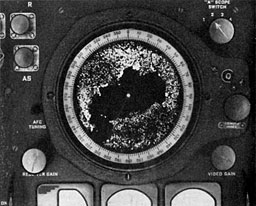
Figure 2-36.--The relief map quality of a land mass pattern such as that shown above is characteristic of the scope presentation of APS-15. This view shows the Tokyo Bay area. Note the heavy concentration of bright spots indicating city areas.
--41--
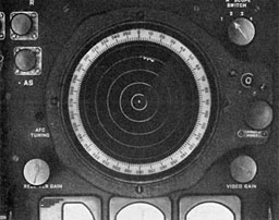
Figure 2-37.--Range marks on the APS-1 5 scope appear as circles of light. This view shows the circles produced when the equipment is set to the 50-mile range. Note the convoy just inside the 40-mile circle at a bearing of 10°.
particularly land masses, produce scope images with a fidelity which compares favorably with a relief map of the region. See figure 2-36.
3. Range settings.--At calibrated intervals along the trace, bright spots can be made to appear, which, as the trace rotates, produce evenly spaced circles on the scope screen. These circles or range marks assist in judging approximate target ranges. See figure 2-37.
Four operating ranges are provided-5, 20, 50, and 100 miles.
| Ranges |
Number of
range marks |
Interval between
range marks |
| 5 |
5 |
1 mile |
| 20 |
4 |
5 miles
|
| 50 |
5 |
10 miles
|
| 100 |
5 |
20 miles
|
C. SPECIAL FEATURES. AN/APS-15 incorporates in its design certain special features which increase the effectiveness of its use for search, navigation, and pattern bombing. They are:
-
Open center control.
-
Antenna tilt.
-
Automatic tilt stabilization.
-
Automatic azimuth stabilization.
-
Manual sector scan.
-
Automatic sector scan.
-
Electronic lubber line.
-
Altitude determination.
-
Drift determination.
-
Precision ranging.
-
Sweep delay selector.
-
Beacon homing.
1. Open center control.--At close ranges (5 to 20 miles), targets around the center of the screen may be somewhat crowded. In order to
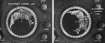
Figure 2-38.--APS-15 incorporates in its design the feature of automatic azimuth stabilization. Above, left, is shown the scope presentation with automatic azimuth stabilization switched off. Here zero degrees indicates the heading of the aircraft and all targets appear relative to the aircraft's heading. At the right the same pattern is shown when automatic azimuth stabilization is turned on. The land pattern has shifted to its true geographic location with respect to the top (zero degrees) of the scope, which is north. The electronics lubber line indicates this heading of the aircraft.
--42--
separate these targets, an "Open Center" control has been provided. Operation of this control makes it possible to move the start of the trace outward from the center of the screen which, in effect, very noticeably expands the presentation of these scope images originating from targets close in.
2. Antenna tilt.--By manual control of a motor-driven mechanism the antenna assembly can be tilted from 20° above to 20° below the horizontal axis of the aircraft. Control of antenna tilt enables the operator to vary the angle at which the antenna beam travels outward around the aircraft. Angles of tilt are indicated on a tilt meter located on the panel of the receiver-indicator unit.
Tilt affects range. With low angles of tilt, the area traversed by the beam is small; with high angles of tilt, the area traversed can be extended to the limits of the horizon.
With a fixed tilt setting it is possible that changes in the flight attitude of the aircraft will cause the transmitted antenna beam to shift from a target area during successive sweeps of the antenna. To counteract this effect, automatic tilt stabilization may be employed.
3. Automatic tilt stabilization.--Automatic lilt stabilization employs a gyro system connected to the till mechanism in such a way that when the antenna is manually adjusted to any preset angle by the tilt switch, this angle of tilt will be maintained regardless of limited (20°) changes in the aircraft attitude of flight, within a range of 20° above or below the horizontal axis oil he plane.
4. Automatic azimuth stabilization.--When the automatic azimuth stabilization feature of AN/APS 15 is used, information from the aircraft's flux-gate compass is related to the motor-driven mechanism of the antenna spinner so as to cause the indicator sweep rotation to be oriented with respect to true north. As a result, t a rget patterns are displayed on the scope screen oriented with respect to true north, and they remain so oriented regardless of changes in the heading of the aircraft. See figure 2-38.
5. Manual sector scan.--By means of switches mounted on the control unit, the normal 360° rotation of the antenna spinner can be interrupted to provide manual control of antenna movement. Operation of the "L-R" switch causes the antenna to rotate left or right, at will. This is particularly helpful when a target indication in a specific sector is to be inspected more closely and more quickly than is possible with the 360° rotation. See figure 2-39.
6. Automatic sector scan.--Sector scanning a specific area can be accomplished automatically. Suitable controls on the control unit permit any sector of the full 360° to be selected, while other controls regulate the width of the sector scan. Both automatic sector scan and automatic azimuth stabilization can be employed simultaneously to display the scanned sector on the scope in its true relationship to north.
7. Electronic lubber line.--Employment of this feature produces intermittently a line of light on the scope whose azimuth position indicates the heading of the aircraft. A micro-switch aligned with the fore-aft axis of the aircraft controls electronic circuits in the equipment which produce a line of light on the scope screen each time the spinner sweeps past the dead-ahead position. See figure 2-40.
8. Altitude determination.--Two features of design assist the AN/APS-15 operator to determine the absolute altitude of his aircraft be-t ween the limits of 10,000 to 36,000 feet, with an accuracy of ±100 yards. They are the A-scope on the receiver-indicator and the altitude
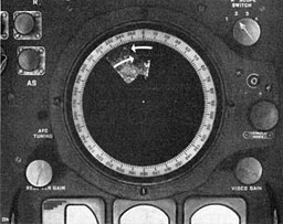
Figure 2-39.--Where a specific area is to be searched the APS-15 can be set to sector scanning (either manual or automatic) causing the antenna to scan the transmitted beam back and forth over the desired area. On the scope only the area being scanned appears as a radar image.
--43--
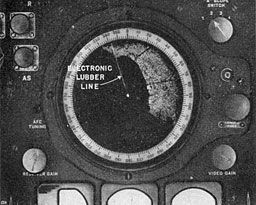
Figure 2-40.--The use of the electronic lubber line on the APS-15 provides a quick and accurate indication of the aircraft's heading. When automatic azimuth stabilization is used the heading indicated by the electronic lubber line is true as shown above. When automatic azimuth stabilization is not used the electronic lubber line when switched on will appear at zero degrees.
control on the computer unit. When the range unit is switched on, a downward projecting pip, called the altitude pip, is developed near the left end of the A-scope's horizontal trace. Rotating the altitude control on the computer unit shifts the position of the sea return on the A-scope trace. When the sea return is moved so that its left edge is in coincidence with the altitude pip, the absolute altitude of the aircraft is indicated by the position of a sliding index hairline along a vertical scale on the computer box. (With the AN/APS-15 A or AN/APS-1515, the minimum altitude that can be determined accurately is 3,000 feet.)
9. Drift determination.--An estimation of drift is possible when the automatic azimuth stabilization and electronic lubber line features are used. The scribed movable azimuth index line located over the face of the PPI is rotated so as to align it parallel to the movement of the pattern on the scope screen. The angle this line makes with the electronic lubber line is an indication of the aircraft's angle or drift.
10. Precision ranging.--Use of the range unit, computer box and control unit produces a range circle on the PPI which can be used to indicate the slant range to targets up to a distance of about 45 miles with an accuracy of ± 150 yards. See figure 2-11.
When the factors of absolute altitude, ground speed, drift, and type of bomb are known and (he equipment is adjusted accordingly, the time for bomb release is indicated when the selected target moves in along the scribed azimuth index line (set to represent course) to coincide with the slant range circle.
As a reverse function, the slant range circle can be coincided with a target or signal to denote its slant range.
11. Sweep delay selector.--Sweep delay is a design feature incorporated in AN/APS-15 which allows the start of the trace on the PPI and PRI to be delayed in 10-mile steps, up to a total of 200 miles. When this feature is used in conjunction with the equipment's normal ranges of 5, 20, or 50 miles, the trace then represents the outer portion of the extended area; e. g., if the sweep delay is set to introduce 150 miles of delay and the equipment is set to the 50-mile range, the trace will represent coverage of the last 50 miles of a 200-mile area.
12. Beacon homing.--To enable the AN/APS-15 to trigger X-band radar beacons and receive their signals, the AN/APS-15 must be reset from the search function to beacon
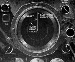
Figure 2-41.--Operation of the ranging feature of APS-15 produces a slant range circle on the PPI scope which can be employed for precision pattern bombing of a selected target. The bomb release point is indicated when the selected target moves down to the slant range circle as produced by setting the equipment for correct altitude, drift, and ground speed.
--44--
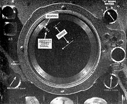
Figure 2-42.--On PPI type scope presentations a beacon signal appears as a series of vertically space dashed lines. Their number and separation denotes the code employed. Range to the beacon is measured from the center of the PPI to the lower edge of the innermost dash.
operation. When so adjusted, the receiver-indicator may be retuned, not to the radar pulse-and-echo frequency, but to the transmission frequency of the X-band radar beacon transmitters, such as AN/CTN-6. As a result, radar echo signals do mil appear on the scope screen. The radar beacon signals appear correct in azimuth and range. [dentity is indicated by the coding of I he beacon signals. See figure 2-42.
The range circles for the 5-, 20-, 50-, and 100-mile ranges can be employed to denote approximate range to a beacon station. By employing the sweep delay feature, beacon signals up to 250 miles away (50-mile range setting plus 200 miles delay) can be detected. The maximum distance that can be displayed on the scope is 250 miles, because the sweep delay selector settings operate only in conjunction with the basic 5-, 20-, and 50-mile range settings on the indicator. It must he remembered that maximum ranges are dependent upon the aircraft's altitude and the line-of-sight distance to the beacon transmitted (see Range, Part III, p. 18).
When more accurate ranging is required, the range unit may be switched on. The slant range circle may then be employed to indicate the exact range to the beacon station. Precision ranging is possible only to 215 miles. Since the maximum radial distance which can be represented by the slant range circle is 15 miles, this figure added to the maximum of 200 miles delay obtainable from the sweep delay selector setting will produce a circle which represents a range of 200 plus 15, or 215 miles.
III. TACTICAL EMPLOYMENT
The tactical employment of AN/APS-15 and the effectiveness with which it contributes to the success of a mission depends in large measure upon the skill of the operator in employing any or all of the features incorporated in its design and in interpreting the scope patterns produced as a result of the use of those features.
A. SEARCH. 1. Types of targets.--In search operation, targets may be classified either as single spots or as relatively larger patterns which are produced by land masses.
At long ranges (50-, 100-mile range settings) the size of a target spot on the scope cannot be interpreted to indicate with any degree of accuracy whether the target spot has been produced by one target such as a single ship, or many ships in convoy. It is only after range has been closed that closer inspection of such target spots will reveal the number of targets.
Similarly, the size of the target spot is no definite indication of the actual relative size of
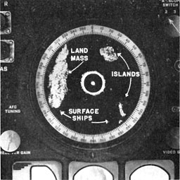
Figure 2-43.--The above view of the APS-1 5 scope gives an excellent indication of land mass, island, and surface ship targets. The circular pattern around the center of the scope is caused by sea-return reflections.
--45--
the target. Large ships bow-on or stern-to may cause target indications on the scope of the same size that smaller ships beam-to will produce.
Images of land masses, coastal areas and islands are faithfully reproduced on the AN/APS-15 scope screen with a degree of fidelity almost approaching that of a relief map. See figure 2-43. Mountainous or rugged terrain areas will stand out more sharply than flat areas. Coast lines are well defined. At long ranges, cities appear as concentrations of light on the scope pattern at a greater intensity than the surrounding areas. Rivers and harbors can be identified. Specific buildings amongst many cannot be identified.
Thunderheads, because of their great moisture content, reflect radar echoes and cause distinctive patterns to appear on the scope screen. These patterns resemble those of land somewhat in that they are fairly solid, but have fuzzy, indistinct edges. The upward tilt of the antenna required to pick up "fronts," plus the fact that reference to charts of the area will determine whether land echoes can be expected, will assist in identifying fronts as such.
Because echoes from weather fronts are as bright as echoes from other types of targets, heavily clouded areas clutter the scope, tending to mask target areas. This and heavy precipitation may mask more distant radar echoes, tending to reduce the effective range of the equipment.
For the study of echoes due to weather, the A-scope of the AN/APS-15 should be used in conjunction with the PPI for the following reasons:
(a) The A-scope permits a study of small variations or changes in amplitude of a returned echo which ordinarily would be masked out on the PPI. The A-scope accurately shows the relative signal strength of returning echoes. The relative density of clouds can be determined from this information.
(b) Due to the high persistence of the PPI's fluorescent screen, a sudden change is not as apparent on the PPI as on the A-scope.
(c) The A-scope measures contours of clouds better than the PPI scope. On the PPI, two or more clouds relatively close together would appear as one large cloud. On the A-scope, however, there would be a noticeable separation between the echoes returning from the two clouds.
2. Altitude/range.--The range at which targets may be displayed on the scope depends almost entirely on the aircraft's altitude. At an altitude of 2,000 feet, the line-of-sight distance to the horizon is about 50 miles. At this altitude, even though the 100-mile range is used, surface targets at distances greater than 50 miles will not be seen. (See altitude chart, fig. 2-17.)
Altitude plays an important part not only in determining the area covered by the sweep of the beam but also in producing adequate resolution and definition of a target. Land mass targets observed at low altitudes generally are not as well defined on the scope as the same targets observed at greater altitudes. A limiting factor, however, is the production of a larger sea return as the altitude is increased. Large sea returns tend to mask targets close at hand. From a practical standpoint, some balance must be struck between large sea return at high altitudes as weighed against better resolution of targets at the higher altitudes.
3. Conversion of slant to horizontal range.-- Any radar equipment deals in slant ranges. From the computer drum can be read the distance which represents the hypotenuse of a right triangle of which the vertical distance from the airplane to the ground is one side and the horizontal distance from a point directly beneath the airplane to the target is the other side. The difference between slant range and ground range is negligible whenever the range is more than five tiihes the altitude, but for targets close by, the difference of slant range versus actual range must be taken into consideration if an accurate range indication is required.
4. Tilt control and flight attitude.--Tilt control, tilt stabilization, and automatic azimuth stabilization all contribute to clarity of target definition and to the ability to maintain a target indication on the scope, regardless of limited maneuvers of the aircraft.
--46--
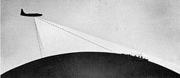
Figure 2-44.--When searching at lower altitude the antenna tilt must be raised in order to
increase the radar horizon range.
Tilt is not critical for targets which are already within the beam; but in order to pick up targets which are beyond the beam coverage, the antenna must be tilted upward. Particularly with respect to aircraft targets, the upper edge of (lie beam must be raised by means of 1 be tilt control iii order to include such targets in the beam's coverage. See figure 2-44. The tilt control also functions to insure that with de-crease in altitude the beam may be progressively raised to keep the target in the area covered by i he beam.
5. Ranges of detection.--The actual ranges at which targets may be observed depend upon such factors as:
-
Varying performance of individual equipments.
-
Operator skill.
-
Altitude.
-
Type and composition of target.
-
Intelligent use of tilt control.
The following table of average ranges to be expected for various types of targets is indicative only in a general way of what can be expected in the use of AN/APS-15:
| Target |
|
Naut. miles |
| Large coastal cities |
|
95 |
| 5,000-ton ship |
|
40 |
| Harbor buoys |
|
15 |
B. NAVIGATION. 1. Aids to precision navigation.--Because of the high-fidelity, maplike scope presentation of prominent land masses which are produced when AN/APS-15 is set for search, and the display of code-identified beacon signals when set for beacon reception, precision navigation is one of the main uses to which AN/APS-15 equipment can be put. A number of design features contribute to precision navigation:
When set for Search
(a) The electronic lubber line shows the heading of the aircraft. (See figure 2-45.)
(b) The scribed azimuth index line, when aligned parallel to target movement across the scope screen, can be used with the electronic lubber line to indicate angle of drift.
(c) With the slant-range circle feature, precision ranging on a given target can be conducted over a measured period of time to calculate absolute ground speed.
(d) Azimuth stabilization allows viewing of a truly oriented maplike land mass area for comparison with charts of the same area.
(e) Knowing the above, a collision course with a selected target can be established.
When set to Beacon
(f) Relative bearing of beacon stations can be ascertained by lining up the scribed index line with the center of the coded signal and noting its azimuth position with respect to the
--47--
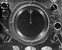
Figure 2-45.--When it is desired to home on a target such as a point of land as indicated in the view above the use of the electronic lubber line will assist in maintaining the heading of the aircraft toward the selected target.
azimuth indicator scale around the periphery of the scope.
(g) Use of azimuth stabilization will orient the beacon signals on the scope to their true geographic location.
(h) By the use of the sweep delay sector feature, beacon station signals up to a range of 250 miles can be received, provided the aircraft is flying at an adequate altitude. (See line-of-sight chart, figure 2-17.)
(i) Precision ranging on beacon station signals permits accurate interpretation of slant range to the beacon up to approximately 215 miles.
2. Homing: Radar targets.--All of the factors affecting target resolution and definition, such as altitude, range, antenna tilt, terrain contour, and weather, enter into a consideration of effective homing.
Heading and drift determine the track which must be maintained if it is desired to set a collision course for homing on a specified target. See figure 2-45. When a target in a specific area has been selected for homing purposes, the job can be simplified through the use of the electronic lubber line, azimuth stabilization and sector scanning. Use of the range marker circles will assist in approximating target ranges. Use of the slant range circle (within a range of 45 miles) will denote accurate target range.
3. Homing: Beacon targets.--The factors outlined in the preceding paragraph apply to a limited degree in homing on the signal from a radar beacon station. The exception is that with radar beacon signals the reception ranges are greater than for target echo ranges. This is because a radar beacon signal is a directly transmitted powerful signal while the target echo is a weak reflection of the original radar transmission. Also, a radar beacon station, if it is in operation in the area being patrolled and within range, produces a coded signal on the scope screen, to furnish a positive indication of the beacon transmitter's identity, range and bearing. See figure 2-46.
C. BOMBING. 1. Pattern bombing.--At the altitudes at which AN/APS-15 may be employed for bombing, 10,000 to 36,000 feet, the target areas must necessarily be general in nature. The equipment is suitable for pattern bombing-not for bombing of specific objects.
Through overcast, or under conditions of poor or zero visibility, AN/APS-15 can furnish information on:
-
The aircraft's ground speed.
-
The aircraft's angle of drift.
-
The aircraft's true heading.
-
The track to be flown.
-
The closing range of the target area.
From a knowledge of these factors and the
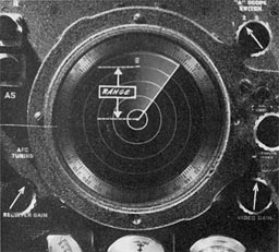
Figure 2-46.--After a beacon signal is picked up the aircraft is turned until the signal appears dead ahead. Range to the beacon may be judged wilh the aid of the range circle.
--48--
type of bomb being used, an operator can determine, through the use of the slant range circle, when the bomb-release point has been reached.
2. Absolute ground speed and drift angle.-- Although AN/APS-15 can be employed to determine absolute ground speed and drift angle, it should not be relied upon solely to furnish this information when other means are available. Rather, AN/APS-15 ground speed and drift information should be used to supplement and cross-check the data provided by other proven means.
3. Low-altitude bombing.--Although the equipment is designed for bombing from altitudes above 10,000 feet, it can be used for low-altitude bombing when fitted with a lowT-alti-tude antenna reflector which is supplied with the equipments. However, because it is difficult to follow the target on the PPI at ranges of less than 1 mile, AN/APS-15 is suited to low-altitude bombing only when the proper release point can be determined visually.
NOTE.--A new series of air-borne search radars, designated as an APS 30 Series, is under development to replace generally AN/APS-3 and the AN/APS-15 series. The AN'/AI'S .'!<! series consists Of two basic equipment and two alteration kits, as follows:
AN/APS-31 is an X-band search radar containing many of the special features of design and operation contained in AN/APS-15. Its antenna scans through a forward-looking field of view producing a scope presentation of a 160° V on a PPI-type scope.
AN/APS-32 consists of a kit of antenna and other essential replacements which when used with the AN/AI'S-31 changes it from X-band operation to K band operation.
AN/APS-33 is an X-band search radar similar to AN APS-15 and AN/APS-31, but furnishing either a full 360° PPI-type presentation or a 60° V-type presentation, the apex of the latter appearing above bottom center of the scope face.
AN/APS-34 is a change over kit for use with AN/APS-33 to change it from X-band operation to K-band operation.
AN/APS-15A AND AN/APS-15B
NOTE.--The function, uses, description and tactical employment of AN/APS-15A and AN/APS-15B are, in general, the same as those described for AN/APS-15. Therefore, only the changes and improvements incorporated in the AN/APS-15 A and AN/APS-15B are described herein.
A. SPECIAL FEATURES OF AN/APS-15A and AN/APS-15B
1. Veeder counter.--The computer unit of the AN/APS-15A and AN/APS-15B models use a Veeder counter in place of the computer drum used in the AN/APS-15, for reading absolute altitude and slant range. The Veeder counter is more accurate, does not have the errors of the computer drum and is easier to read. The counter is calibrated from 3,000 feet up to 90,000 feet (approximately 15 miles).
2. Ranges and range markers.--The AN/ APS-15 A and AN/APS-15B models provide two fixed operating ranges-zero to 50 and zero to 100 miles. A third range is continuously variable between the limits of 5 and 30 miles. To assist in judging approximate ranges to a target, a range selector switch enables the operator to select any one of three sets of range circles for any one of the three operating ranges. The circle separation is as shown in the following table:
Number of
range marks |
|
Interval between
range marks |
| |
100-MILE RANGE |
|
| 10 |
|
10 |
| 20 |
|
5 |
| 100 |
|
1 |
| |
50-MILE RANGE |
|
| 5 |
|
10 |
| 10 |
|
5 |
| 50 |
|
1 |
| |
5- TO 30-MILE RANGE |
|
| 1 to 3 |
|
10 |
| 1 to 6 |
|
5 |
| 1 to 30 |
|
1 |
3. Sweep timing.--In the AN/APS-15, the open center control was employed where it was necessary to expand the display of targets crowded close to the center of the PPI screen. In the AN/APS-15A and AN/APS-15B, the sweep timing control, in addition to being used as a means for expanding the pattern (see Open Center Control, p. 42), also operates to contract the screen pattern. Operation of the sweep timing control makes possible the elimination of
--49--
the blank area in the center of the PPI which occurs when flying at the higher altitudes, thus allowing the entire scope face to be utilized for viewing targets. Also, in those cases where a portion of a target image appears at the extreme outer edge of the scope screen, manipulation of the sweep timing control shrinks the scope pattern, bringing the target echo within the boundaries of the scope screen.
4. Precision ranging.--With AN/APS-15A and AN/APS-15B, precision ranging on objects up to approximately 100 miles is possible. When the bomb release marker is adjusted to
coincide with the target image on the PPI screen, the distance to the target is that shown on the computer counter (in feet) plus the delay set in by the sweep delay selector (in nautical miles). For targets within a range of 15 miles (maximum limit of the range circle), it is not necessary to employ sweep delay.
5. Bomb release point data.--In pattern bombing, 12 separate counter dials are supplied with the computer unit, any one of which may be selected for insertion in the unit, depending upon the type of bomb employed, and different indicated air speeds.
--50--
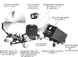
--51--
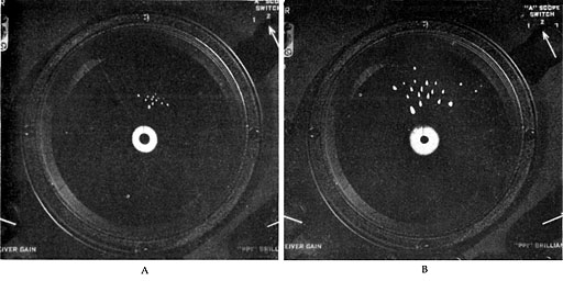
Figure 2-47.--The AN/APS-2 (or George) series of PPI type radars display scope presentation similar to the APS-1 5 but not with as high a degree of target resolution A, above shows a convoy while B shows the same convoy at a lower range setting. C and D are characteristic land mass presentations.
ASG-AN/APS-2 SERIES
NOTE.--The ASG-AN/APS-2 series of air-borne radars-ASG, ASG-1, AN/ASP-2 (ASG-3), AN/APS-2A (ASG-2), AN/APS-2B (ASG-2), AN/APS-2C (ASG-3), AN/APS-2D, AN/APS-2E-are somewhat similar In design and identical in function, the design differences arising chiefly from changes in mounting dimensions and mounting methods to adapt the equipment to the type of aircraft in which installation is being made. The AN/APS-2D and AN/APS-2E, in addition, substitute an "open center control" in place of the PHI focus control on the receiver-indicator, the latter control being removed to the PRI itself. The models in this series are the forerunners of the AN/ APS-2F and AN/APS-15 radar equipments. The section on AN/APS-2F which follows is applicable in general to all of the ASG-AN/APS-2 models. Those items marked with an asterisk (*) represent features incorporated in the AN/APS-2F which are not contained in the earlier equipments.
I. FUNCTION
A. PRIMARY PURPOSE. AN/APS-2F is an S-bancl radar designed primarily for general airborne search operations in heavy patrol aircraft.
B. SECONDARY USES. AN/APS-2F may be employed for navigation, beacon homing, and, when used in conjunction with other electronic equipment, it may be employed for target identification.
II. DESCRIPTION
A. MAIN COMPONENTS. The main units of AN/APS-2F are:
-
Transmitter-converter unit.
-
Rotating antenna-spinner assembly.
-
Receiver-indicator, bousing the operator's viewing (PPI) and monitoring (A) scopes.
-
Repeater (PRI) scope, for pilot or navigator use.
-
Control unit.
B. ANTENNA SCAN AND SCOPE PRESENTATION. In general, the operating clia racterisl ics of AN/ APS-2F and its antenna scan and scope presentation are identical with AN/APS L5 (see p. 39), with the following exceptions:
-
AN/APS-2F operates in the S-band of frequencies.
-
Its antenna beam is a 9° cone.
-
Its operating ranges are identical with AN/APS-15 (5, 20, 50, 100 miles).
C. SPECIAL FEATURES. AN/APS-2F incorporates in its design certain special features
--52--
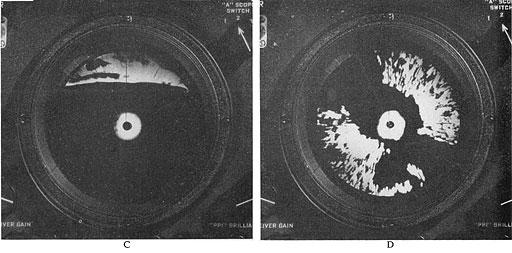
Fig. 2-47C&D
which enhance its value for search and navigation use. They are:
-
Antenna tilt.
-
Automatic tilt stabilization.*
-
Automatic azimuth stabilization.*
-
Manual sector scan.
-
Automatic sector scan.*
-
Automatic frequency control.*
-
Electronic lubber line.*
-
Beacon operation.
-
Open center control.
III. TACTICAL EMPLOYMENT
A. SEARCH. 1. Types of targets.--Target definition and resolution are not as good as that obtained by the AN/APS-15 (see p. 39), due to the relatively lower operating frequency iS hand) employed by the AN/APS-2F, and to the 9° beam as compared to the 3° beam width of the AN/APS-15.
2. Tilt.--The AX APS 2F antenna produces a 9° conical beam which must be controlled by the tilt switch to keep it on a target. Because of the limited coverage obtained by the beam, antenna tilt is critical. The ability to keep targets in the beam is dependent upon altitude and the intelligent use of the tilt control, particularly as the range to the target is closed. Also the 9° conical beam (as compared to the beam spread in the vertical plane produced by the special antenna design of the AN/APS-15) results in limited coverage, in depth, of land masses as displayed on the scope. This, too, is a function of altitude and correct antenna tilt.
3. Range settings.--Operating ranges are the same as for AN/APS-15 (5, 20, 50, 100 miles).
B. NAVIGATION. 1. Homing.--Homing on targets and beacons is the same as for the AN/ APS-15. Precision ranging (as in the case of AN/APS-15) is not possible since a range unit is not included in the AN/APS-2F equipment. Full reliance must be placed on the use of the range marker circles for judging target and beacon signal ranges.
When set for Beacon, the AN/APS-2F operates in conjunction with the AN/CPN-3 (YK) radar beacons. Range coding, as displayed on the PPI, denotes identity, and the position of the indication on the scope screen gives the range and hearing of the radar beacon.
Dependent upon altitude, radar beacon signals are receivable up to the maximum range (100 miles) of the equipment.
C. BOMBING. Bombing with AN/APS-2F is essentially a matter of employing any or all of the special features of this equipment in order to home on a target to within visual contact.
(For low-altitude precision bombing with AN/APS-2F see AN/APQ-5B. Part II, p. 83).
--53--
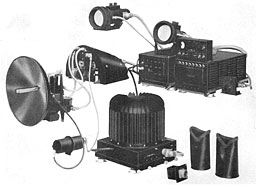
AN/APS-3
--54--
AN/APS-3
NOTE.--The AN/APS-3 is a later model of the ASD, ASD-1 series.
I. FUNCTION
A. PRIMARY PURPOSE. AN/APS-3 is an X-band air-borne radar employed primarily for search in medium patrol aircraft.
B. SECONDARY USES. This equipment can be used for radar navigation, homing on radar beacons (AN/CPN-6) and for radar bombing. When employed in conjunction with other suitable identification equipment it can be used to display IFF signals. (See Part IV, page 113.)
II. DESCRIPTION
A. MAIN COMPONENTS. AN/APS-3 consists of the following major units:
-
Antenna unit.
-
Transmitter-converter (r-f head).
-
Modulator unit.
-
Receiver amplifier.
-
Rectifier unit. 0. Control unit.
-
Azimuth calibrator.
-
Repeater indicator.
-
Connector cables, viewing hoods, and dummy indicator,
R-F head.-- The inclusion of the radio-frequency head in the AN/APS-3 design overcomes one of the main drawbacks to efficient operation so pronounced in the earlier ASD version of the equipment.
In the ASD (for purposes of comparison) the generated pulses were fed from the modulator to I he antenna through a long, complicated wave guide which both from a mechanical and electrical standpoint was inefficient. As a result, the effective power was attenuated before reaching the antenna.
In the AN/APS-3, part of the transmitter and receiver circuits are moved up to the r-f head, which is located close to the antenna. The transmitted pulses pass through a short wave guide direct to the antenna with no appreciable attenuation. Received echoes likewise pass through the short wave guide to the preamplifier located in the r-f head, where they are demodulated before being passed to the remainder of the equipment through flexible coaxial cables; thus, the long, inefficient wave guide is eliminated.
B. ANTENNA SCAN AND SCOPE PRESENTATION. 1. Beam coverage.--The antenna unit consists of a parabolic reflector and antenna feed assembly connected to a motor-driven gear box so that the antenna and parabola are mechanically and electrically caused to sweep an arc of 160° ahead of the aircraft at a repetition rate of about 35 cycles per minute. The parabola nods over an arc of 2° from the horizontal during the sweep.
The antenna-parabola assembly projects the r-f pulses in a conical beam of approximately 5°.
As the antenna sweeps the r-f beam through its 160° of arc (80° either side of center), a nodding action is imparted to the parabola at the completion of each sweep, resulting in a nod downward of 2°, a sweep of 160°, a nod upward of 2°, the return sweep, etc. Although the azimuth sweep angle is 160°, only 150° of this angle is calibrated, as 5° are used at each end of the sweep for the nodding action.
2. Type of scan.--Two scopes are provided; one is the main scope for the operator's use, the other, the auxiliary scope for pilot or navigator use. Both scopes are of the B-scan type. (When either scope is removed from the installation, it must be replaced by the dummy
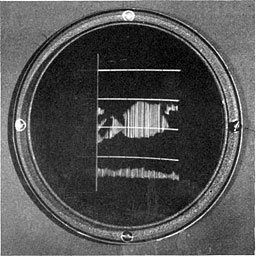
Figure 2-48.--In APS-3 the side-to-side motion of the trace
produces a rectangular scope display on the circular scope face.
--55--
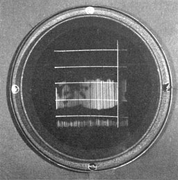
Figure 2-49.--Variations in the brilliance of the laterally moving trace activates the fluorescent coating of the cathode-ray tube indicator producing the target patterns. Above is shown a typical landmass pattern as it appears when the equipment is set to the 10-mile range.
indicator so as not to disturb circuit characteristics. )
The effective 150° of lateral scan of the antenna assembly is translated on the scope into a lateral motion of a vertical trace which moves from side to side in step with the antenna motion, to cover a rectangular area on the scope face. See figue 2-48. The conversion of an angular antenna scan into a rectangular scope display introduces certain disadvantages due to distortion effects (see B-scan distortion, figs. 2-9, 2-10, 2-11, and 2-12), but the advantages of spreading the display of targets close in far outweighs the inherent distortion disadvantages.
Reception of target echoes causes the moving trace to brighten momentarily in its lateral sweep. The bright spots on the trace appear on the scope screen at a range and azimuth corresponding to the target's range and bearing from the searching aircraft. Because of the persistence of the fluorescent coating of the scope screen, target echoes displayed on the scope remain visible for a short period of time after the trace has swept by. Each succeeding trace sweep renews the target echo brilliance. Single ship or aircraft targets are displayed as small spots of light. Land masses, islands, coast lines, etc., show up as relatively large patches of light. See figure 2-49.
3. Range settings.--At the control unit, when the beacon-search switch is set for search operation, the equipment can be used on four ranges of 4, 10, 40, and 80 nautical miles. When set for beacon operation, the ranges are 4, 10, 40, and 120 nautical miles.
As the trace moves from side to side on the rectangular screen, bright spots appearing at graduated intervals along the trace leave a trail behind them to form range markers. These range markers assist in judging the approximate range of target echoes. See figure 2-50.
| Range (miles) |
Number of
range markers |
Range mark
intervals (miles) |
| 4 |
3 |
½ |
| 10 |
5 |
2 |
| 40 |
4 |
10 |
| 80 |
4 |
20 |
| 120* |
6 |
20 |
| *Beacon only. |

Figure 2-50.--The horizontal lines on the scope patterns shown here are brilliant lines of light
which enable the operator to judge target range.
--56--
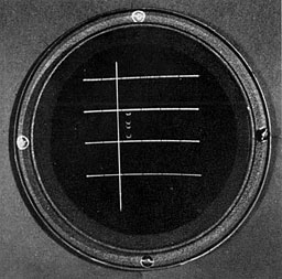
Figure 2-51.--A typical beacon signal appearing on the 40-mile range of the APS-3.
4. Bearing.--To indicate bearing, the rectangular screen is covered with a plastic scale containing seven scribed vert ical lines. These lines divide the 150° screen into three 25 sections either side of zero degrees at the vertical center. The zero-degree line represents the ail-craft's heading.
C. SPECIAL FEATURES. A number of special design features contribute to the flexibility of use of AN/APS-3. With the exception of one--the azimuth calibrator--all these special features are controlled from the panel of the control unit. They are:
-
Antenna tilt.
-
Beacon reception.
-
Expanded sweep (with electronic lubber line and azimuth calibrator).
-
Phantom target.
1. Antenna tilt.--By means of a toggle switch control located on the control unit panel, the beam from the antenna can be tilted through a vertical range 8° above and 8° below the longitudinal axis of the aircraft. Degree of tilt is indicated on the control unit tilt meter. Tilt control enables the beam, with its 2° nod, to cover an area 24° in the vertical plane.
2. Beacon reception.--Controls are provided (beacon-search switch and manual timing) which permit the equipment to be retimed to the X-band radar beacons for reception of radar beacon signals. When the. equipment is switched from search to beacon operation, the manual timing control must be employed to retune the receiver away from the radar's pulse-and-echo frequency to the frequency of the radar beacon (AN/CPN-6). When this is done, radar target echoes do not appear on the scope screen. Only radar beacon signals from beacon stations within range are displayed. See figure 2-51.
3. Expanded sweep.--When the expanded sweep is employed, the scope presentation appears over the entire circular area of the scope screen instead of in the form of a rectangle. This operation "magnifies" or expands the center area of the scope so that only the central 60° portion of the rectangular pattern is displayed.
With the "expand"' feature being used, an electronic lubber line flashes on the screen each time the antenna scanner passes the dead-ahead position. See figure 2-52.
An azimuth calibrator control can be employed to shift the position of the electronic lubber line. When the electronic lubber line is aligned with a target echo, the dial of the azimuth calibrator will indicate the bearing of the
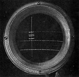
Figure 2-52.--Here the range-coded radar beacon signals appear on the expanded sweep scope display.
Positioning of the electronic lubber line allows the relative bearing of the beacon to be accurately determined.
--57--
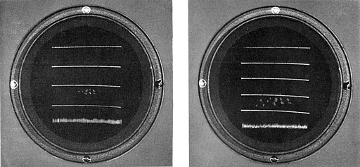
Figure 2-53.--At the left a convoy is shown at about 16 miles on the 40-mile range setting of the AN/APS-3.
At the right, the same convoy is shown when the range has closed to the 10-mile range is used.
target with respect to the heading of the aircraft.
III. TACTICAL EMPLOYMENT
A. SEARCH. When employing AN/APS-3, the prime consideration to be borne in mind is that the narrow 5° beam, like a searchlight, "illuminates" only those targets that fall within the path of the beam.
Whether or not the radar beam will strike a target depends upon:
-
The altitude of the search aircraft.
-
The range of the target.
-
The antenna tilt.
1. Types of targets.--Depending upon the character of the radar echo spots, the screen display can be interpreted to indicate land masses, islands, coast line, harbors, rivers, airports, and surface ships. Land is indicated on the screen as a relatively large bright patch of light. Coast lines and harbors appear distinctly outlined, but, because of the distortion effect inherent in the B-scan, the scope display of such targets is not a true replica of the actual coastal outline. Rivers and lakes show up as dark areas within the bright land mass patches.
Ships in convoy, at long ranges, produce target spots which appear on the scope as one large spot or as a group of indistinct spots closely bunched together. As the range is closed, however, and the shorter ranges of the equipment used, the group tends to break up into separate, distinct target spots. See figure 2-53.
At extremely close ranges, a single ship target echo will appear on the screen as a long, horizontal line of light, ragged in appearance.
2. Altitude/range.--With the aircraft in level flight, the antenna of AN APS-3 points to the horizon when the tilt meter indicates zero tilt. Depending upon the altitude, then, intermediate distances to the horizon can be covered only when the antenna is tilted downward, or when the altitude is reduced.
3. Tilt control.--Because of the comparative narrowness of the beam (5°), tilt control of the AN/APS-3 is critical. As a general rule, operation of AN/APS-3 requires that tilt control be employed almost continuously in order to insure adequate coverage of the area being searched. This is particularly true as the range settings are altered. For instance, for any given altitude, low angles of title will be required to search the area immediately ahead of the aircraft when the 4-mile range setting is employed; but if the equipment is set to any one
--58--
of the higher range settings, the tilt must be moved upward in order that the radar beam may encompass the more distant areas.
Target definition can be improved in many cases if, after the target appears on the screen, the tilt control is employed to "aim"' the beam directly on the target area. Then, as the range is closed, successive adjustments of downward tilt are necessary in order to keep the target in the beam.
B. NAVIGATION. Because the AN/APS-3 scope screen presentation is maplike in character, radar navigation is relatively simple of accomplishment. Again, the only disturbing factor present is the distortion inherent in the rectangular presentation of a fan-shaped area.
1. Drift determination mid homing on targets.-- When either a radar target or beacon signal is homed on. dri ft will be apparent if the signal shifts from the central lubber line. The degree of drift can be determined by adjusting the flashing lubber line to bisect the target echo. Degree of drift is read from the dial of the azimuth calibrator.
To home on a selected target, the aircraft is maneuvered until the target appears on the centrally scribed (0°) lubber line. After a period of time, the aircraft's drift will be indicated by the movement of the target away from the zero-degree lubber line, and the course is corrected to compensate for the drift. This course correction will put the target echo on the opposite side of the lubber line from that at which it was observed at the time of drift determination. With the new heading maintained, the electronic lubber line can be set to bisect the new target position. As the aircraft is homed on the target, the echo will move down the electronic lubber line (parallel to the zero-degree line) as the range is closed.
Homing on one of many closely positioned targets is simplified by the use of the "expand" function of AN/APS-3. When this function is employed, the central 60° of the full 150° sweep is displayed over the entire circular area of the scope screen and, in effect, spreads apart or magnifies the target display.
2. Homing: Beacon.--When set for beacon operation, AN/APS-3 will display radar beacon signals from beacons located as far away as 120 miles. To receive radar beacon signals, however, the AN/APS-3 must be retuned to the beacon frequency and the aircraft pointed in the general direction of the known beacon stations. Also, to pick up beacon signals at 120 miles the altitude must be such that the beacon station will be within the aircraft's radar horizon.
Received beacon signals appear on the scope screen as a vertical series of short horizontal lines which are range coded. See figure 2-51. At the extreme ranges, the lines will tend to merge together but, as the range is closed, they will separate to show the range coding by wmich the radar beacon station is identified. Hominy on a radar beacon signal is similar to othei radar homing techniques.
C. BOMBING. Low-altitude bombing of radar targets presupposes the employment of a homing procedure such as that previously described. In this connection, deviations from the collision course must be watched for, particularly within the last mile.
When the expanded scan is used, the echo will broaden considerably and its center is the only reference point of value. Tilt and gain controls must be used constantly to get best target definition. With normal gain, the target will leave a slight "tail," in appearance much like a comet's tail, as it moves down the screen. This can be used in determining a collision course, since the tail must be parallel to the zero line if target bearing remains unchanged.
--59--
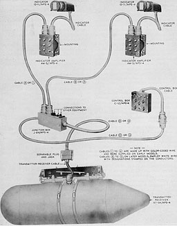
AN/APS-4
--60--

Figure 2-54.--With the APS-4 set for search its antenna executes a two-line scan. When the equipment is set for intercept the scanned area is broadened vertically, the antenna executing a four-line scaninng pattern.
AN/APS-4
I. FUNCTION
A. PRIMARY PURPOSE. AN/APS-4 is an airborne X-band radar employed mainly for search. Its simplified construction allows it to be used in almost any type of aircraft.
B. SECONDARY USES. AN/APS-4 contains control and design features which permit its use for aircraft interception. In addition, it can be used for radar navigation, radar beacon homing and radar bombing. When used with appropriate 1W equipment, it will furnish display of identification signals.
II. DESCRIPTION
A. MAIN COMPONENTS. The AN/APS-4 consists of the following pieces of equipment, plus interconnecting cables:
-
Transmitter-receiver.
-
Control box.
-
Indicator (two indicators for multiplace aircraft).
-
Indicator-amplifier (two indicator-amplifiers for multiplace aircraft).
-
Cable junction box.
1. The antenna scanner, transmitter, receiver, and rectifier power supply are mounted in a laired, pressurized bombshell similar to the Mark 17 bomb. This entire unit is supported in a bomb rack for either wing, or under-the-fuse-lage mounting. In an emergency situation during flight where the security of the radar equipment is endangered by the possibility of its falling into enemy possession, the entire bomblike container may be jettisoned.
2. Only the control unit, indicator scopes, indicator amplifiers, and junction box are mounted within the aircraft.
B. ANTENNA SCAN AND SCOPE PRESENTATION. 1. Beam coverage.--a. The antenna beam is a 6° cone and may be tilted by manual control from 10° above, to 30° below the longitudinal axis of the aircraft in which it is installed.
b. On search, the 6° conical antenna beam scans through 150° in azimuth and executes a two-line scan, with a 4° nod, to cause the beam to cover 10° in a vertical plane.
C. On intercept, the beam executes a four-line scan, with 6° between lines, to cover a vertical plane of 24°. See figure 2-54.
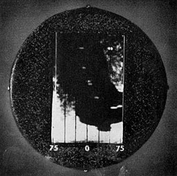
Figure 2-55.--A scope presentation of the APS-4 when set for the 20-mile range. The dark area represents a bay while the light area represents the land on either side. Note the surface ship targets in the convoy proceeding up the bay.
--61--
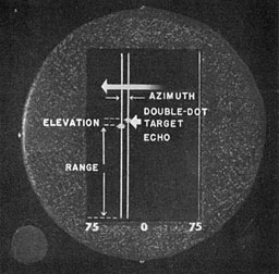
Figure 2-56.--The APS-4, when set for intercept, produces a double, laterally moving trace.
An aircraft target is shown as a double dot.
2. Type of scan.--a. B-scan.--When set for search, the B-type scan presents target images on a rectangular (3-inch) screen. Single targets are displayed as single spots of light. Land masses, coast lines, islands, etc., are displayed as relatively large patches of light having the general contour of the actual area being scanned. The distortion typical of B-type scans is present in the AN/APS-4 scope display. See figure 2-55.
A plexiglass filter located over the face of the indicator cathode-ray tube contains scribed vertical lines at intervals of 25° either side of the zero-degree or lubber line, to assist in judging target bearing. The position of the search aircraft is considered to be at the bottom of the central (zero degree) scribed line.
When set for beacon reception the AN/APS-4 indicators display the range-coded beacon signals to indicate the identity, range, and relative bearing of the beacon transmitter.
b. H-scan.--On intercept, the scope dislay, figure 2-56, is of the H-type scan. A target within the field of the antenna beam (150° in azimuth and 24° in the vertical plane) will produce an echo which appears on the indicator screen as two dots of light. The left dot is termed the echo pip, the right clot is termed the shadow pip. The position of the echo pip on the screen indicates the target's range and relative bearing. The position of the shadow pip relative to the echo pip shows the target's elevation. The intercept function of AN/APS-4 permits the interceptor aircraft to be maneuvered so as to put the target aircraft dead ahead and in the line of fire.
3. Range settings.--AN/APS-4 has four operating ranges which are identical for both search and beacon operation-4, 20, 50. and 100 miles. Range marks, instead of being horizontal lines of light as in other B-type scans, are a series of brilliant light spots which appear only at the extreme right vertical edge of the scope screen each time the antenna scanner reaches the limit of its sweep to the right. See figure 2-57.
Range
(nautical miles) |
Number of
range marks |
Range
mark interval |
| 4 |
4 |
1
|
| 20 |
2 |
10
|
| 50 |
5 |
10
|
| 100 |
10 |
10
|

Figure 2-57.--APS-4 has four operating ranges of 4, 20, 50, and 100 miles.
The range marks produced by each of the ranges are shown above.
--62--
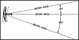
Figure 2-58.--The fill of the APS-4 transmitted beam can be controlled manually
from 10° above the horizontal to 20° below the horizontal.
C. SPECIAL FEATURES. 1. Antenna tilt.--By means of a control located on the panel of the control box. the antenna reflector may be tilted so as to cause the 6° beam to tilt from 10° above to 20° below the aircraft's line of flight. See figure 2-58. The nodding action of the antenna is independent of any setting of tilt. In other words, for any setting of antenna tilt, the antenna will execute a two-line, 4° nod on search, and a four-line 6° nod on intercept.
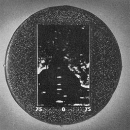
Figure 2-59.--Another view of the convoy proceeding up the bay as shown on the APS-4. Here the antenna has been tilted downward so as to focus the beam on the ship targets. As a result the land mass pattern loses some of its definition.
2. Warning light.--A warning light located on the control box may be set so as to flash when a target echo appears on the screen. During those periods when the operator may be unable to devote his entire attention to the indicator screen, the warning light may be set to indicate the presence of targets.
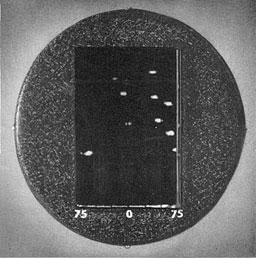
Figure 2-60.--Ships in convoy as seen on the 4-mile range setting of the APS-4.
III. TACTICAL EMPLOYMENT
A. SEARCH; B. NAVIGATION; C. BOMBING. Tactically, the AN/APS-4 may be employed in the same way and for the same purpose as the AN/APS-3 (see p. 55) with the exception that the additional feature of intercept is provided.
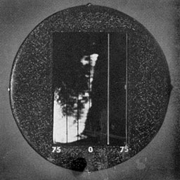
Figure 2-61.--Coast line as it appears on the 20-mile range setting of the APS-4.
--63--
D. INTERCEPT. On intercept, the interceptor aircraft is maneuvered so as to get the target or echo pip on the central (zero-degree) lubber line with the shadow pip horizontally aligned with the echo pip. So long as the target aircraft remains in the field of the antenna beam the target pips will appear, regardless of evasive tactics employed. As the range is closed, both pips will move downward on the screen until visual contact can be made with the target aircraft.
Except under ideal conditions where the target aircraft is retained within the beam scan of 24° in elevation, the intercept feature of AN/ APS-4 is limited in its use and as a rule is never employed for long periods of operation.
--64--
[BLANK PAGE]
--65--
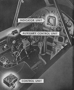
AN/APS-6
--66--
AN/APS-6 SERIES
NOTE.--AN/APS-6 and AX/APS-6A are identical in operation with the exception that AN/APS-6 is designed so that it may accommodate two indicator seniles instead of one as in the AN/APS-6A.
I. FUNCTION
A. PRIMARY PURPOSE. AN/APS-6 is an airborne (night-fighter) radar designed expressly for the dual function of search and interception. It operates in the X-band of radar frequencies.
B. SECONDARY USES. AN APS 6 on search develops a B-scan scope display which can be employed for purposes of navigation, I. c. making landfalls, recognizing land masses and islands, and selecting surface targets on which to home. It can also he used for radar beacon homing and ( when suitable identification equipment is employed in connection with it) for the display of IFF signals.
II. DESCRIPTION
A. MAIN COMPONENTS. The main units of AN/APS-6 are:
-
Antenna scanner unit.
-
Transmitter-converter unit.
-
Indicator unit.
-
Control unit.
-
Auxiliary conl rol unit.
-
Modulator.
-
Rectifier-power supply unit.
-
Receiver amplifier.
1-2. The antenna scanner unit with its associated transmitter-converter is faired into the right wing of the aircraft.
3-4-5. Inside the aircraft, the indicator unit is mounted in the instrument panel while the control unit and auxiliary control unit are mounted convenient for pilot operation.
6-7-8. All other units (requiring no adjustment or manipulation) are installed in remote sect ions of the fuselage.
B. ANTENNA SCAN AND SCOPE PRESENTATION. beam coverage.--On search, the antenna mechanism imparts an outward-inward spiralling motion to the rotating (1.200 r.p.m.) antenna scanner, to cause the 6° beam to cover a conical area of 12(1° ahead of the aircraft's line of flight. See figure 2-63. When the equipment is set to the gun-aim function, the spiralling motion is removed and the antenna revolves to produce a fixed cone of t5° along the aircraft's line of flight. See figure 2-64.
2. Type of scan.--a. B-scan.--AN/APS-6 when set for search, will produce a typical B-scan type of scope presentation, see B-scan, fig. 2-8), on its 25- and 65-mile operating range.
Depending upon the altitude of the aircraft and the range setting of the AN/APS-6 controls, surface and air-borne targets will be displayed in the normal B-scan manner if such targets are within the field of the spiralling beam. See figure 2-65.
O-scan.--When the range switch is set to either the 1- or 5-mile range, the scope presentation is automatically changed from a B-scan presentation to the O-scan or double-dot display. The O-scan presentation is employed mainly to display aircraft target echoes to indicate the relative range, azimuth, and elevation of the target. See figure 2-66.
Surface targets such as land masses, islands, ships, etc., if they are within the 120° field of
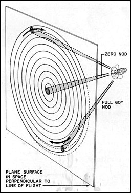
Figure 2-63.--When set for search, the APS-6 antenna spinnei covers a
conelike area of 120 ahead of the aircraft.
--67--
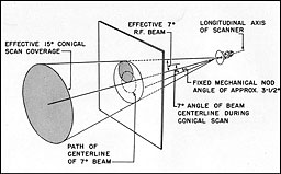
Figure 2-64.--When set for intercept, the conelike area is reduced to 15°.
the beam, will appear on the scope screen somewhat as in the B-scan type of presentation with the exception that all targets are resolved into the double-dot presentation and therefore will appear as an indistinct so-called double-exposure pattern. Other aircraft within the field of the beam will appear in the double-hot manner at their true azimuth positions on the screen.
c. G-scan.--When the auxiliary control is set from search to gun aim. the scope presentation is changed to a G-scan (see G-scan, p. 17). The target echo, which is represented as a single dot on the scope, will appear only when the target is within the beam at a range of 1,000 yards or less. The position of the spot with respect to the center of the scope face denotes the target's range (within 1,000 yards), its bearing and its relative elevation.
As the range between interceptor and target aircraft is closed, the target dot grows horizontal wings. When the interceptor aircraft is maneuvered to place the target spot at dead center, and the range is closed to make the'tips of the wings touch the scribed index lines the target is bore sighted at a gun-firing range of 250 yards. See figure 2-67.
3. Altitude mark and sea necklace.--In addition to target echo display, two separate so-called sea returns are produced. One, a horizontal fuzzy line of light appearing upward from the bottom of the screen, is caused by direct reflection of echoes from the sea immediately below the interceptor aircraft. Its position varies with the altitude of the aircraft and provides a rough indication of absolute altitude. It is called the altitude mark.
The other sea return appears as indistinct, changing lines of light (commonly referred to as the "sea necklace," or "lace curtain"), arranged in a curved pattern which seems to hang from the top of the scope screen. It represents the return of echoes from the sea ahead of the aircraft, increasing and diminishing in size in step with the outward and inward spiralling motion of the antenna scanner. Its maximum-minimum size is a function of aircraft altitude and the range setting of the equipment. See figure 2-68.
--68--
In cases where target echoes above the sea return tend to become masked by the sea return, a "sea suppress" control enables the operator to cut out the central lower portion of the lace curtain.
4. Range settings.--The control unit contains a master range switch which allows the equipment to be set to any one of four operating ranges. They are G5 and 25 miles for search, 5 and 1 miles for intercept. When set for beacon reception, the same range settings denote ranges of 1, 5, 25. and 100 miles.
The auxiliary control unit contains a two-way toggle switch which throws the equipment from the 1- or 5-mile intercept ranges to the 1,000-yard gun-aim range. (When using the equipment for search or intercept, the auxiliary control toggle switch must be set to search.)
The AN/APS-6 scope is not furnished with a calibrated range scale. Target ranges for all four range settings must be judged with respect to the appearance of the target echo up from the bottom of the rectangular scope screen. See figure 2-69). The position of the interceptor
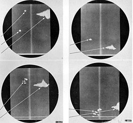
Figure 2-65.--APS-6 search patterns. Top, left, 65-mile range shows convoy, island and coast. Top, right, shows same convoy and island at 20 and 15 miles, respectively. Lower left, /same targets on the 25-mile range. Lower right, 25-mile range. Lower right, 25-mile range; convoy at 3 miles, island at 8 miles.
--69--

Figure 2-66.--On either the 1- or 5-mile range setting of APS-6 an "O" type scan presentation is produced. At the left the double-dot presentation shows that the target is about 40° port and below the intercepting aircraft. (Above, center.) The intercepting aircraft has been maneuvered to bring the target dead ahead. At the right the target is still dead ahead but the range has been closed.
aircraft is assumed to be at the lower center of the rectangular screen. The top of the screen represents ranges of 1, 5, 25, or (55 miles, depending upon the setting of the range switch.
For beacon-signal reception the maximum range is 100 miles.
C. SPECIAL FEATURES. Certain shortcomings in design and operation of the earlier AIA equipment (forerunner of the AN/APS-6 series) dictated the need for a more versatile night-fighter radar. The AN/APS-6 contains the required improvements, as follows:
1. The transmitter-converter unit is pressurized, permitting operation of the equipment at altitudes as high as 30,000 feet. (AIA was not pressurized.)
2. Location of the transmitter-converter in the radome, close to the antenna, permits the use of a short wave guide with a resultant increase in operating efficiency. (The AIA used a long wave guide from the antenna to the transmitter in the fuselage, which introduced signal attenuation.)
3. Four search-intercept operating ranges of 1, 5, 25, and 65 miles are provided.
4. Automatic frequency control of beacon tuning is provided. (In the AIA, tuning to beacon signals had to be performed manually.)
5. AN/APS-6 contains a wing calibrate adjustment which permits the pilot initially to adjust the size of the wings of the gun-aim scope presentation. The adjustment consists of flying the night fighter 250 yards behind a friendly plane (as determined by reference to the optical gun sight) and adjusting the size of the gun-aim wings on the target spot until the wing tips just meet the vertical lines scribed on the indicator face. (AIA did not contain this adjustment.)
6. In the AN/APS-6 B-Scan presentation, the separation of the double dots is such as to produce a sharp, easily definable indication of target elevation. (The AIA lacked a sensitive display in the double-dot presentation which made evaluation of target elevation difficult.)
III. TACTICAL EMPLOYMENT
A. SEARCH. When specifically employed for search, AN/APS-6 enables the pilot of a night-tighter aircra ft to observe all manner of targets within a wide area ahead of the aircraft up to the maximum range of the equipment. Large ships have been picked up as far away as 50 miles. Land targets are seen up to 65 miles in range, and aircraft are regularly seen to the limit of the 5-mile range.
B. INTERCEPT. AN/APS-6, although suitable for use in general search operations, is particularly well adapted to night interception of hostile aircraft. When specifically employed for intercept operations of this nature, the fighter aircraft, after being air-borne, is vectored by the intercept officer at the controlling station (CIC of the fighter director ship or ADCC of the shore control station), to put the intercepting aircraft on the enemy's tail.
--70--
During the closing phase, the interceptor aircraft can employ the search function of AN/ APS-6 on the 65-mile or 25-mile ranges to assist in picking up the target. When the range has been closed to within 5 miles, the range setting is switched to the 5-mile range and. as the range is closed to within 1 mile, to the 1-mile setting. On the 5- and 1-mile settings, the scope presentation presents the target in the characteristic double-dot style to indicate the target's relative range, bearing, and elevation.
When climbing or diving on a target, the latter may appear to be at the same elevation as the interceptor since it is in line with the
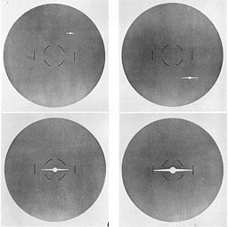
Figure 2-67.--When APS-6 has been set to the gun-aim function a type-G scope presentation is produced. The target image will appear as a small dot whose relation to the center of the scope indicates azimuth and elevation of the target. By maneuvering the aircraft the spot can be made to appear at the center of the scope. As the range closes the spot will grow wings. When the wings touch the scribed lines on either side of the horizontal center of the scope the target aircraft is at firing range.
--71--
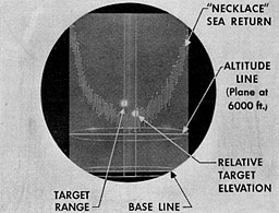
Figure 2-68.--As the spiralling motion of the APS-6 antenna causes the beam to strike the sea ahead of the aircraft, a series of reflections are returned to the aircraft which cause the characteristic sea return called "sea necklaces." Another series of reflections from the sea directly below the aircraft produces an "altitude line."
interceptor's longitudinal axis. However, because of differences in the course and speed of the two aircraft, prolonged maneuvers of this sort may result in: (a) moving the field of the radar beam off the target with consequent loss of target indication; (b) overshooting the target and disclosing the interceptor's presence, thus loosing the element of surprise; or (c) in the need for excessive corrective maneuvers requiring violent course and speed changes.
Climbing or diving maneuvers employed by the interceptor to put him on the tail of and at the same level as the target aircraft should be performed in steps, leveling off at the completion of each step to observe the target's new relative elevation.
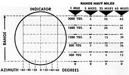
Figure 2-69.--The APS-6 can be set for any one of 4 ranges. The scope face, however, is not graduated in terms of range and target distances must be estimated as shown above.
C. GUN AIM. The gun-aim function of AN/APS-6 should not be used until it is certain that the target aircraft is within 1,000 yards in range and at the same elevation as the interceptor. At 1,000 yards, or less, the target will be within the radar beam and its echo will show on the scope screen to indicate its relative range, bearing, and elevation.
If the range to the target should open because of too sudden decrease in speed of the interceptor aircraft or increase in speed of the target aircraft, or if evasive maneuvers of the target aircraft take it out of the conical beam, the spot of light will appear to snap quickly to the center of the screen where it will remain motionless. In such cases, the gun-aim switch must be set to search in order that the interceptor aircraft may again observe the target on the 1- or 5-mile intercept ranges and maneuver his aircraft into gun-aim range.
During the period of interception on either the 1- or 5-mile ranges, an attempt should be made to ascertain the target's speed so that the range may be closed gradually. Too fast an "overtake" may put the target aircraft out of the cone of fire, or it may result in actual collision.
D. NAVIGATION. As is the case with other air-borne radars employing a B-scan scope

Figure 2-70.--Typical beacon coded signals, 100-mile range.
--72--
presentation, radar navigation with AN/APS-6 is a matter of recognizing surface targets or land masses as such, and employing the information thus obtained for the purpose of navigating from one point to another, making landfalls, or establishing a course with respect to recognizable reference points.
AN/APS-6 displays targets according to the B-scan type of scope display only on the 65- and 25-mile ranges, when set for search.
When the equipment is set for radar beacon reception, the B-scan displays beacon signals (when within range of the beacon transmitter), as a series of range-coded spots which appear on the scope correct as to range and bearing. The coded arrangement of the signal presentation establishes the identity of the beacon transmitter. See figure 2-70.
--73--
[BLANK PAGE]
--74--
GENERAL APPLICATIONS OF RADAR
I. INTRODUCTION
Because they lend themselves to a diversity of uses other than those for which they were primarily designed, air-borne radars have become one of the most effective of tactical weapons. Even under the most perfect of flying conditions, the information they are capable of providing is often superior to that obtained by visual means; in other cases, radar becomes a valuable source of supplementary information with which to cross check information received visually. Under adverse conditions of reduced visibility or total darkness, radar is often the only source of information available to pilot, navigator, and bombardier.
Regardless of the specific purpose for which a given air-borne radar has been developed, there are certain factors concerning its tactical employment which are common to all air-borne radars. The following section describes certain features of operation and employment which apply generally to all search-type airborne radars.
II. RECONNAISSANCE AND PATROL
A. GENERAL. 1. Conditions of visibility.--Radar is especially effective under conditions of low visibility, but even in good weather it should be used at all times for search. Though it is true for practical purposes that, with visibility unlimited, the human eye can reach out nearly as far as the radar, it is not true that the human eye can give as efficient coverage of an area.
Small targets that blend with the color of the sea are likely to be missed by the eye, but the ability of radar to detect targets is not affected by camouflage. Targets into the sun are difficult to gee, particularly when the sun is low on the horizon; and a slight haze sometimes cuts down visibility without being noticed by the crew. Radar functions regardless of conditions of visibility. Visual search depends upon the continued alertness of the aircraft's crew at all times; radar will detect targets whenever they are within radar range. On the other hand, crew members should not abandon visual alertness because of the use of radar. The two, used together, insure the most efficient coverage of an area during search.
2. Range.--The factors which affect range are: (a) altitude, (b) power, and (c) to a limited degree, equipment break-down ceilings.
a. Altitude.--The maximum effective range of the radar equipment will be dependent upon the aircraft's altitude relative to the range settings of the equipment. In other words, even if a radar is set to operate on its 100-mile range, it will not be able to detect targets at this range when its flight altitude is so low that the radar horizon extends only to a maximum of 50 miles. The chart, figure 2-17, on page 19 gives the radar line-of-sight distances to the horizon for various altitudes.
b. Power.--The power of an air-borne radar equipment constitutes one of the prime factors which limit operating range. Echo reception at long ranges is dependent upon the ability of the equipment to transmit pulses which will be powerful enough to cover the distance from the radar to the target and to produce an echo of sufficient strength to complete the return trip. In this connection, therefore, once the maximum range as defined by the power limitations of a particular radio equipment itself has been reached, a further increase in range will not be effected merely by increasing the altitude of the searching aircraft.
c. Radar equipment operation ceilings.--Because certain parts of air-borne radars operate at extremely high values of voltage and are subject to electrical break-down at the low atmospheric pressures encountered at high altitudes, pressurizing safety precautions have been incorporated in the design of some equipments to maintain them at pressures comparable to those at the safe operating altitudes. The altitude limitations or "break-down ceilings" for the several types of air-borne radar equipments are listed in column 8 of the table on page 145.
B. AREA SEARCH. In planning radar search operations a medium range setting of the equipment should be chosen so as to insure adequate echo reception from small targets. The altitude at which the search aircraft is to be flown in order to provide this range coverage should
--75--
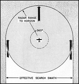
Figure 2-71.--In conducting a search operation with the PPI type of radar
equipment, the effective swath of an air search leg is determined by the altitude
at which the aircraft is flying and its radar range to the horizon. |
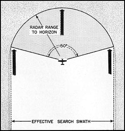
Figure 2-72.--In aircraft equipped with radars employing the B-type scan, only the
area immediately forward and to the sides of the aircraft are scanned, as shown
here. Because of the 150° sector scan, the actual search swath is somewhat
less than the search swath area produced with the PPI type of equipment. However,
here, too, the effective width of the search leg is determined by the altitude of
the aircraft and its radar range to the horizon. |
be high enough to insure that the radar horizon is just slightly beyond the maximum range employed.
The search aircraft, if equipped with either the L-type or PPI-scan radar will sweep a search swath whose width will be twice the effective range of target detection (see fig. 2-71). In laying out area searches when using the B-scan type of equipment, however, it must be remembered that here the scanner sweeps an area extending only to 75° either side of the dead-ahead position. This results in a search swatli which is somewhat narrowed in width (see fig. 2-72). The swath thus produced by the field of coverage (making allowances for a certain amount of overlap) will dictate the number of legs to be flown in order to cover a specified search area.
For example, a search mission may involve the use of an aircraft fitted with AN/APS-3 search radar. Consistent, reliable target pickup, it may be found, is obtained on the equipment's 40-mile range setting. The line-of-sight table (p. 19) indicates that an altitude of 1,000 feet will produce a radar horizon at a distance of about 38 miles. This is safely within the 40-mile range setting. A conservative range at which a wide variety of targets will be displayed by the equipment is about 35 miles. This is still within the 38-mile radar horizon. Allowing for the fact that the oscillating antenna sweeps through 150° of arc (75° each side of dead ahead) and thus does not cover the full 35-mile distance either side of the aircraft, the maximum side area may be considered to be approximately 10 percent less or about 31.5 miles. This means that the air-borne radar is safely covering an area ahead and to either side of the aircraft to a distance of approximately 31 miles. If the search area to be covered is some 360 miles on a side, then allowing for a small amount of overlap for successive legs, some six legs will have to be flown, in order to cover the entire area. See figure 2-73.
In cases where patrol craft are equipped with loran, the problem of area search is greatly simplified if full use is made of the loran charts in laying out the various legs of a search area (see Tactical Employment of Loran, p. 140).
--76--
C. SECTOR SEARCH. Planning sector searches involves the employment of the same planning procedure as for that of area searches. The maximum range of detection is estimated for the types of target expected, and the appropriate flight altitude is determined for such range.
In addition, however, the sector search depends upon meeting the coverage requirements--
1. Where the sector angle is specified: The length by the sides of the triangle will be determined by the search swatli of the air-borne radar.
2. Where the distance to be flown from carrier or base is specified: Keeping in mind the restrictions imposed by the search swath area, a sector angle must be chosen to provide complete coverage of the sector search area.
Figure 2-74 illustrates condition 1, wherein for a given sector angle the range from base must be calculated to avoid excessive overlap on the one hand and an uncovered area on the other.
Figure 2-75 illustrates condition 2. Note that for a given distance from carrier or base the sector angle must be such that complete coverage of the area may be accomplished.
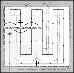
Figure 2-73.--When planning a search of a specified area, consideration must be given to the width of the search legs so that the number of legs to be flown can be calculated to adequately cover the entire area, allowing for a slight amount of overlap between adjacent legs.
D. ANTISUBMARINE SEARCH. This type of search proceeds much as any other except that the assumed radar horizon will be less and the searching altitude lower. At close ranges, most radars can detect submarines when only their periscopes show.
Because it is possible for submarine targets to detect the presence of search aircraft by tuning in on the radar pulses, it is advisable, once an unidentified target is detected, to employ the search radar intermittently.
III. NAVIGATION
A. DRIFT. 1. Drift compensation methods.-- When an aircraft is directed toward a target
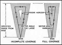
Figure 2-74.--Where a given sector angle for a search is specified in the operating plan, the altitude of the aircraft and the length of the legs must be determined to provide a search swath which will adequately cover the area to be searched without producing incomplete coverage.
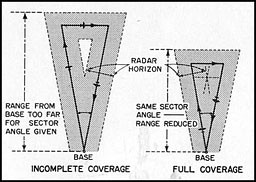
Figure 2-75.--Where the range of a given area is specified, the altitude of the aircraft and the angle of successive legs must be determined to provide a search swath which will adequately cover the area to be searched without producing incomplete coverage.
--77--
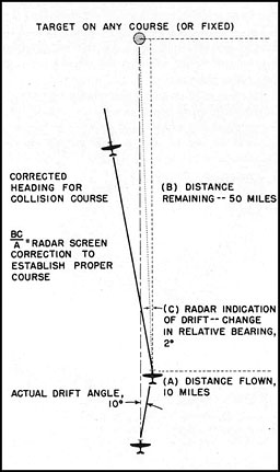
Figure 2-76.--A method as described in the text for determining correction for drift by radar.
and the heading is thereafter held constant, a gradual change in the bearing of the target echo as observed on the scope indicates drift. If the echo moves to the left of the lubber line, the aircraft's drift (not the target's drift) is to the right, and vice versa. The direction of drift is easily determined, but compensating for drift is more difficult.
Two radar drift compensation methods are described, as follows:
a. Method 1.--To determine the amount of drift, a radar target is selected and the aircraft is maneuvered so as to place the target on the lubber line, preferably near the top of the scope screen, and the range to the target is noted. Then for a selected distance, the course is maintained, during which time (if drift is present) the target, in addition to moving down the screen, will also move to one or the other sides of the lubber line, depending upon the direction of drift. By multiplying the observed drift in degrees by the distance in miles yet to be flown to intercept the target, then dividing the product by the distance flown during the check period of observation, a result, in degrees, will be obtained which indicates the required change in heading that must be made in order to compensate for drift and to maintain a collision course with the target. (See fig. 2-76.)
b. Method 2.--(This method is not adapted to L-scan (ASB) radar equipment.) If an aircraft is headed directly toward a target and a constant course maintained, drift causes the radar echo to change in bearing. The amount of change depends upon the range at which the aircraft was first headed toward the target and the distance subsequently traveled. By employing the graph (fig. 2-77), the angle of drift can be determined.
The procedure for using this graph is as follows:
Note the range when the target is dead ahead.
Maintain this heading until the target has changed in bearing by 5°. Then note the target's new range.
Along the bottom of the graph, locate the vertical line corresponding to the range at which the 5 drift was indicated. Then along the left edge of the chart locate the horizontal line corresponding to the initial range noted.
At the point of intersection of the selected horizontal and vertical lines the drift angle is indicated by the degree Line that passes through this point of intersection or by an interpolated line estimated by eye to the nearest whole degree.
As an example of the use of this chart: A target is observed dead ahead at a range of 40 miles. A constant heading is held until the target has changed by 5°. At this point, the range to the target has closed to 25 miles. Employing the graph, the 25-mile vertical line along the bottom of the graph is selected, and along the left edge of the graph a horizontal
--78--
line corresponding to the original 40 miles is located.
It is found that these two lines intersect at a point on the graph which is crossed by the 8° drift line. This indicates the aircraft's angle of drift.
The successful use of this method depends upon the operator's ability to read fairly accurately a bearing of 5° to left or right of the zero-degree line. AVith the AN/APS-3, the expanded sweep should be employed and the flashing lubber line set to 5° left or right, depending on the direction of drift. As soon as the echo is centered under this Bashing lubber line, the second range reading is taken.
With the AN/APS-15, the aircraft is maneuvered until the target echo is placed dead ahead. The direction in which the echo drifts is noted and the scribed azimuth index line is rotated 5° in the direction of drift. Again range is noted as soon as the target is centered under this new position of the azimuth index line.
With map-type radars that do not have a flashing lubber line or a movable azimuth index line, the 5° position must be estimated. On all map-type radars, it is necessary to use the center of the echo as the point from which to determine the bearing. A broad land mass is not a suitable target unless it has a projection or indentation that produces a radar target which may be employed as an easily noted point of reference.
Ship targets are not reliable for determination of drift since a change of bearing may be caused either by wind or ship motion or both.
2. Surface wind checks.--There are many times during (light over open water when no targets are in sight. In such cases, the two methods of drift determination above described cannot be successfully employed, since they require the use of a fixed target. With certain radars, however, an experienced operator can make a fair estimate of the direction of surface wind and a very rough estimate of its velocity, provided the aircraft is at an altitude of about 1,000 to 1,500 feet. Because winds at higher altitudes may differ from near-surface winds, the information obtained is of value only for low-altitude flights.
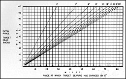
Figure 2-77.--Another method for determining drift by radar is through the use of this chart,
as described in the text.
--79--
Since the wind at and near take-off point is usually known, the size and appearance of the sea return should be observed closely as soon as the aircraft is at flight altitude and on course. Subsequent changes in both direction and intensity of the wind produce changes in the appearance of the sea return on the scope screen. This change takes the form of an enlarged sea return on the upwind side because the larger surface of the waves present a greater reflecting area to the transmitted pulses of the radar. With practice, such changes in sea return pattern can be interpreted to indicate roughly wind direction and velocity.
B. ABSOLUTE ALTITUDE. On most radars the sea or ground return can be used to indicate an aircraft's approximate absolute altitude, the degree of accuracy obtainable varying with the type of radar used. As a general rule, none are affective for this purpose when the absolute altitude is less than 1,500 to 2,000 feet. For this reason, radar altitude acts best as a check upon having sufficient margin of safety when flying over mountainous territory.
C. COASTAL NAVIGATION. 1. Pilotage.--Following a coast line is quite easily accomplished with the aid of radar and a map of the area. The screen pattern indicates whether or not a course parallel to shore is being flown and position is established from shore line contours, as displayed on the scope.
2. Point-to-point navigation.--On a long flight, point-to-point radar navigation can be used. This means flying a predetermined course and obtaining radar checks of position by observing the identifying characteristics of prominent landmarks such as headlands, harbors, bays, and rivers. Normally, such flights can be flown at great distances off shore. Point-to-point radar navigation is used also for island-to-island flights where an objective is reached by following a string of islands.
This type of navigation requires accurate tracking of the flight and careful map reading. To avoid the possibility of losing the identity of a check point, the ETA for each point-to-point jump should be computed. Unless there are several headlands or other check points close together, the ETA can serve as a cross check on the radar information so as to make identification positive.
When making an approach from the open sea to an island dead ahead, it usually is unwise to head directly in and then make a 90° turn to follow the coast line, because mountains on the island or an enemy garrison may make such an approach dangerous. Rather, the approach should be made tangentially; that is, at a range of from 4 to 5 miles from the island, a 45° turn is made in the desired direction. When the aircraft has closed to the desired distance off shore, another turn is made to place its heading parallel to the coast line.
3. Pin-point radar navigation.--When accurate radar coastal fixes are required or when a radar approach is made to a specific objective, the aircraft should be flown close to the shore and at low altitudes. The range setting of the radar should be such that the target and the immediate area about it covers a substantial part of the scope screen. Optimum conditions for accurate work are about 1 mile off shore and 1,000 feet in altitude. Under these conditions, pin-point radar navigating for mine laying, bombing, or approach of landing can be done. Where possible, the approaches should be planned in advance with adequate attention being given to photo-reconnaissance reports and the use of landfall relief maps so that the objective as displayed by the radar can be readily identified.
D. MINE LAYING. Mine laying at night, where accurate ranges are essential, requires pin-point navigation. Since mining operations usually take place at channel entrances, accurate piloting is required. With the map-type radars (particularly the B-scan type), the actual approach is relatively easy, provided the radar navigation is carefully and accurately planned in advance.
When radar mine laying is conducted by several aircraft it is advisable for the operator in the lead aircraft to perform the radar navigation for the section, all aircraft releasing the mines on a light signal from the leader, thus laying the mines in pattern. The timing of the release must take into account the disposition and spacing of the aircraft in the section so that the center of the pattern is midchannel.
--80--
The method of determining the release point depends both upon the type of radar and the topography of the particular area being mined. If the topography is suitable, the drop is made at a given distance from a point ahead as displayed by the radar, such as the opposite bank of a channel, coral reefs known to jut above the water, or even from channel markers. Under other conditions, it may be necessary to make the drop a certain number of seconds after passing a radar check-point on the required heading. With the map-type radars, a series of photographs of the radar screen taken during a "dry run" by reconnaissance aircraft will prove invaluable for planning mining operations.
IV. RADAR BOMBING
Radar bombing techniques vary widely according to the tactical situation, the type of radar, and the type of aircraft employed. Such bombing may be carried out partly by radar and partly visually; it may be accomplished using the search radar only; or search radar with bombing attachments may be employed. It may involve precision bombing against ships at low altitude: area bombing of enemy bases at medium altitude: or pattern bombing of cities at high altitude.
There are two main radar problems in bombing. The first is the problem of flying a collision course to intercept the target. The second is the problem of accurately ranging on the target to determine the correct release point. At low alt itude or high altitude, these problems are essent ially the same.
A. LOW ALTITUDE BOMBING. 1. Target approach.--The manner in which attacking aircraft approach the enemy depends on many things-disposition of the enemy force, visibility, possibility of interception by enemy night fighters, and other elements that enter into the total tactical situation.
In approaching an enemy task force or convoy for a radar bombing attack, it is usually the case that the ships upon which the attack is to be made are inside a screen of escort ships. It becomes important, then, that the approach be made in such a way as to enable the radar to furnish maximum discrimination between tar-
gets so that any given target within the group may be singled out and attacked. Usually it is desirable to approach a selected radar target within a screen in such a manner that the aircraft does not pass close to a screening vessel. The disposition of the ships should be noted beforehand and the approach made so as to avoid these escorts.
If, at long range, target course can be determined, a beam approach may be possible. Under such conditions, the size of a target can be fairly accurately estimated. Should the approach be modified to suit drift conditions or enemy disposil ion, the final run should be made at a minimum of 3 miles in order to accurately set up a collision course which can be observed by radar.
The altitude of approach, once radar contact with the enemy is established, varies with the tactical situation. To avoid detection by enemy radar over sea areas, a close-to-the-water approach up to about 20 miles should be made, after which correct bombing altitude is regained.
Assuming the enemy can track an approach-ing aircraft with his radar, a straight-in-ap-proach has the disadvantage of letting the enemy know the aircraft is heading directly for him. At this point, a certain amount of deception may be employed to advantage.
Basically, these deceptive measures involve:
If possible, locating the enemy at a radar range of 10 miles or more.
Setting a course that will allow closing with him but will leave him in doubt as to whether an attack is developing.
Turning in to the attack at the last moment, allowing just enough time to establish a collision course for an accurate radar bombing run.
2. Release point.--Low- or high-altitude bombing demands a range precision that is difficult to obtain with search radars not equipped with special bombing attachments. Somewhat of an exception is the ASB radar with which it is possible to determine the release point within approximately 100 feet. The map-type radars have an inherent error introduced by the time interval between successive sweeps of the scanner across the target. This has the effect of
--81--
making the target come down the screen by "steps"' rather than continuously. Successive scanner sweeps may display the echoes as much as 100 to 500 yards apart, depending upon the scanning speed. As the aircraft nears the release point, the step effect becomes a serious drawback, This, along with other inherent difficulties of reading accurate ranges close to the target, indicates that the degree of precision necessary for accurate bombing is neither easily nor reliably obtained from the search radar alone.
3. Torpedo attack.--A knowledge of the target's course and speed is necessary before torpedo attacks are effective. Since radar cannot furnish this information with a reliable degree of accuracy, visual assistance becomes necessary. The radar has a definite use, however, in detecting targets at long range and assisting in making the approach. For the torpedo run, once visual contact is made, radar can be employed to furnish reliable range information which can be used to assist in determining the torpedo release point.
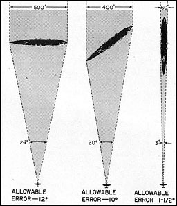
Figure 2-78.--From a bombing standpoint target width as observed on a radar scope is a function of target length and target angle. The above figure illustrates that a beam approach to a target increases the allowable deflection error which is an important factor in the successful outcome of radar bombing.
4. Accuracy of low altitude bombing.--A radar attack presumes that a target cannot be seen visually and therefore, unless target course can be determined, it is difficult to distinguish between length and beam of a ship from its echo on the screen. This introduces two errors in the low-altitude bombing problem--(a) deflection errors and (b) range errors.
a. Deflection errors.--The relative importance of these errors depends largely upon the angle from which the approach to the target is made. In other words, target width is a function of target length and target angle. For example, figure 2-78 shows the effects of approaching from different angles a ship 500 feet long with 60-foot beam. The illustrations show the angular width as seen from a bomb-release point of 400 yards. The allowable error in the collision course is obtained by taking one-half the angle which the outside limits of the target form as seen at the release point. From a study of the illustrations, it is obvious that a beam approach increases the allowable deflection error.
b. Range errors.--Allowable range errors depend upon the target's depth in the line of flight. This, in turn, depends upon target angle. Suppose, with a target having a freeboard of 40 feet and a beam of 100 feet, the approach is made broad on the beam.
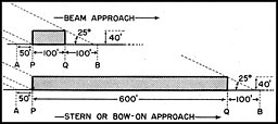
Figure 2-79.--From a consideration of the above figure it will be seen that the range errors are most critical when making a beam approach, lt will be seen that by making a radar approach on a target's beam the element of range error becomes quite critical whereas range error is low for a stern or bow-on approach. Of course, such approaches assume that the radar scope presents information which allows the target's course to be determined, thus making a beam approach or a stern or bow-on approach a matter of choice by the pilot.
--82--
It is known that a bomb released from 300 feet at 180 knots enters the water at an angle of about 25°. Assume as a hit any bomb that lands between points "A" and "B," figure 2-79. By simple mathematics it is found the "QB," for this example, is about 100 feet and gives a total hitting space of approximately 250 feet in the line of flight. Suppose, however, the approach to the target is made from the stern. "PQ" now becomes the length of the ship and the hitting space increases to approximately 750 feet. This example illustrates the obvious fact that range errors become critical when approaches are made broad on the beam.
c. Sources of error.--Deflection and range errors can be attributed to three causes (assuming level flight at the instant of release):
Errors in the radar range, caused by limitations inherent in the radar, possible faulty calibration, and poor interpretation by the operator.
Miscalculation of speed with which the aircraft approaches its target.
Improper altitude at the instant of release.
For any particular bombing run, the errors due to (1) cannot be compensated for.
For (2) and (3) the following must be considered: Deflection errors are less critical for a beam approach to a target than for a head-on or stem-to approach. Range errors on the other hand, are less important for approaches to targets head-on or stern-to than for beam approaches. Range errors can be compensated for in large measure by dropping bombs in train.
B. HIGH-ALTITUDE BOMBING. From a radar standpoint, high-altitude bombing (10,000 to 40,000 feet) requires the use of radars suitable for such work, or parent radars with requisite bombing attachments in order that the required degree of bombing accuracy may be obtained.
As has been stated previously, the problem of high-altitude bombing is essentially similar to that of low-altitude bombing except that the manner of accomplishment does not ordinarily require observance of all of the factors inherent in low-altitude bombing.
Because high-altitude radar bombing requires the use of specific radar equipments or attachments, their mode of use will dictate the manner in which the actual bombing run is to be accomplished. (See AN/APS-15, p. 41, and AN/APQ-5B, p. 91.)
--83--
[BLANK PAGE]
--84--
AIR-BORNE TAIL WARNING RADAR
I. TYPES AND FUNCTION
There are four separate sets of air-borne radar equipments which are designed for the specific purpose of warning aircraft personnel when other aircraft are at close range astern. These equipments, called tail-warning equipments, are:
(For Installation in
fighter planes) |
| (For installation in
patrol bombers) |
| 1. AN/APS-11 |
|
3. AN/APS-16 |
| 2. AN/APS-13 |
|
4. AN/APS-17 |
A. AN/APS-11, AN/ASP-13. The AN/APS-11 and AN ASP 13 are similar except for differences in the electrical circuit arrangement. These radar equipments convert reflected energy from aircraft targets to the rear of the fighter aircraft into an electric current which turns on a red light located near the gun sight and so shielded as not to interfere with other lights on the instrument panel. The red light warns the pilot that another aircraft is within the cone of coverage of the equipment i'.»o wide in a vertical direction and 60° wide in a horizontal direction) and within a range of 200 to 800 yards.
The maximum range of 800 yards was purposely kept low. At ranges greater than 800 yards, the pilot is in no immediate danger from a i ailing plane. Within that distance, however, evasive action becomes necessary if the tailing plane proves to be hostile.
B. AN/APS-16, AN/APS-17. The AN/APS-16 and AN/APS-17 are similar to each other but differ from the AN/APS-11 and AN/APS L3 in range and in the indications they produce. Intended for use in bombers, they are designed to warn the entire crew.
1. In the AN/APS-17, returning echoes from an aircraft astern produce a 1,000-cycle note that is pipped or interrupted at a rate inversely proportional to the range, from 1 pip per second at 3,000 yards to 10 pips per second at 200 yards. In other words, as the range between the two aircraft closes, the repetition rate of the signal pip increases. The warning signal is fed into the interphone system, thus warning all crew members at the same time.
The maximum range is adjustable from 500 to 3,000 yards. The fixed antenna produces a beam whose coverage is a cone 120° wide.
2. The AN/APS-16 has the same range and beam coverage as the AN/APS-17. The indication is a 400- to 1,-100-cycle note which, since its power comes from the aircraft's generators, will vary in pitch with the r.p.m. of the aircraft's engines. The tone is interrupted at a rate inversely proportional to range, from 2 pips per second at 5,0,00 yards up to 10 pips per second at 200 yards.
C. LIMITATIONS ON TAIL WARNING SYSTEMS. 1. One disadvantage in the use of the system lies in the fact that friendly escort planes trigger the warning system into operation every time they fly on or across the tail of the tail-warning-equipped bombers. To surmount this difficulty, the inclusion of identification equipment will make it possible to differentiate between friendly and enemy aircraft.
2. Another disadvantage which is common to all tail-warning equipments is that when the aircraft is flying at low altitudes (at an altitude within the horizontal range of the equipment), the sea or ground return produces a spurious warning signal which could be mistaken for a tailing aircraft. Recommendations have been made to sufficiently alter the design of tail warning equipments so as to eliminate this disadvantageous effect.
--85--
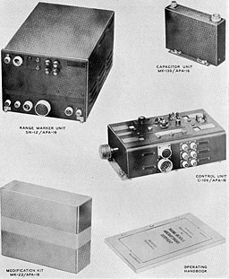
AN/APA-16
--86--
ASSOCIATED EQUIPMENTS
(Bombing Attachments and Airborne Fire Control Radar)
AN/APA-16
I. FUNCTION
The AN/APA-16 is a low-altitude radar bomb sight, designed to facilitate the bombing of surface vessels from aircraft. It operates, in conjunction with parent radars such as the ASB Series, the AN/APS-3 (ASD-1), and the AN/APS-4 (ASH), to compute the release range to a target and to automatically release the bomb when the aircraft reaches the release position.
II. DESCRIPTION
The AN/APA-16 assembly comprises three major units. They are:
-
Control unit.
-
Range marker unit.
-
Capacitor unit.
In addition, a modification kit is required to adapt the AN/APA-16 to the particular radar installation employed.
III. MODE OF OPERATION (for example, with ASB radar)
In explaining the general operation of the AN/APA-16, it is assumed that the echo signal from the target which it is desired to bomb has been located on the screen of the radar indicator.
The AN/APA-16 attachment is triggered from the radar trigger pulse and supplies pulses to the ASB indicator for tracking a selected target and for indicating the release range. The resulting presentation on the ASB indicator screen is in the form of a blanked-out section of the sweep trace. This blanked-out part of the trace is called the range mark. It causes the screen to present an appearance like that of "B" in figure 2-80, or, under conditions of adjustment, like those of "C," "D," or "E."
The leading edge of the range mark, the end nearest zero range, indicates the bomb release range; the lagging edge of this pulse can be set coincident with the leading edge of the echo pulse and, by proper adjustment of the control unit, can be made to "track" the echo pulse, under which condition the computer in the control unit is supplied with the required information as to the relative velocity between the aircraft and the target. The release point is a function of the relative velocity between aircraft and target and the altitude of the aircraft, and is computed by means of electrical circuits.
As the aircraft approaches the target, the blanked-out portion of the indicator sweep between the echo signal from the chosen target and the bomb release point grows shorter and shorter and disappears when the release point is reached. Short sharp pulses coincident with the leading (release range) edge and with the lagging (tracking) edge of the blanking or range marker pulse are also developed in the AN/APA-16 attachment. When these pulses become coincident, as they do on arrival of the aircraft at the release point, they act through a coincidence circuit to actuate the bomb release mechanism.
This equipment, with automatic computer for determining the release point, is designed to operate at altitudes of from 50 to 500 feet and relative velocities of aircraft and target from 50 to 400 knots. Means are provided for adjustment of the release point to enable dropping the first of a train of bombs so that the bombs will "straddle" the target. This same control may be used to correct the dropping point for variations in bomb trajectory due to wind resistance.
--87--
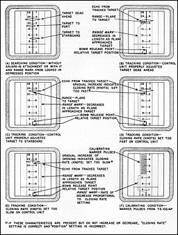
Figure 2-80.--Target indications and range marker blanking on the ASB indicator screen.
--88--
[BLANK PAGE]
--89--
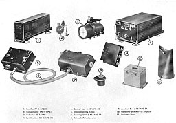
AN/APQ 5-B
--90--
AN APQ-5B
I. FUNCTION
AN/APQ-5B is a low- and high-altitude bombing attachment designed to operate in conjunction with certain airborne radar equipments for the purpose of automatically releasing a bomb (or train of bombs) at such a point that it will hit a desired target. (See Note, p. 84.)
II. DESCRIPTION
The main components of AN/APQ-5B are:
-
Synchronizer.
-
Control unit.
-
Tracking unit.
-
Indicator.
-
Compensator.
-
Rectifier, junction box and capacitor unit. (Also required as accessories are a bond) sight stabilizer and an adapter kit for connecting the AN/APQ-5B to the parent radar.)
III. MODE OF OPERATION
The basic operation of this equipment is as follows:
1. The associated radar equipment produces a train of extremely short hut intense pulses of high-frequency energy and transmits these in a highly directive beam. Remote objects in the path of the beam reflect some of this energy, and a portion of it is intercepted by the antenna. These received echoes ultimately appear as a train of pulses recurring at the same rate as the outgoing train but delayed in time depending upon the distance separating the target from the aircraft. By observing this time delay, it is possible to determine the distance to the target, and by noting the heading of the beam when echoes are received, to ascertain the relative hearing of the object. This information usually is presented on the B- or PPI-scope of the radar.
2. AN/APQ-5B also operates from these video pulses, together with a reference trigger pulse marking the time of the outgoing signal. A separate B-type scope is furnished on which is impressed the target echo and a reference range marker which appears in the center of a one-mile sweep. This range marker and associated sweep can be moved tow>ard zero range at a rate which corresponds to the relative velocity of the aircraft and target. This rate is adjusted during the bombing run so that the target coincides with the reference marker at all times. A release pulse or pip is also generated, which is adjustable in range to correspond to the proper release point of the bomb. This release point is a function of the relative velocity of the aircraft and target and the altitude of the aircraft. When the reference pulse or range marker which is coincident with the target echo arrives at the release point, the electrical addition of this pulse and the release point pulse energizes the elecrical bomb release mechanism and drops the bombs. An 18-mile alternative sweep for the scope is furnished and is employed at the beginning of the bombing run to prevent confusion in the case of multiple targets and to aid in the proper selection of a specific target.
3. The azimuth scale of the B-scope consists of three inscribed vertical cross hairs and the amplitude of the azimuth sweep covers an angle of approximately ±60°. Means are provided to enable the bombardier to set up the course of the bombing run so as to intersect the target regardless of drift conditions. The bombardier has only to maintain the target indication coincident with the central vertical cross hair of the B-type indicator by operation of the usual bomb sight turn controls. This operation controls the automatic pilot mechanism or the pilot direction indicator to alter the heading of the aircraft so that it travels along a collision course to the target.
4. AN/APQ-5B is designed to operate with an automatic computer for determining the release point at altitudes from 65 to 2,000 feet and relative velocities of aircraft and target from 100 to 400 miles per hour. Means are provided for adjustment of the release point to enable dropping a train of bombs centered on the target, and to correct the dropping point for variations in trajectory due to wind resistance. For higher altitudes up to a maximum of 50,000 feet, release distance is not determined automatically by the computer, but must be read by the bombardier from a chart provided for these conditions of altitude and velocity. The reading is set on the control dial manually.
--91--
5. For high-altitude bombing, AN/APQ-5B becomes a semisynchronous impact-predicting bombsight. A maximum of 70,000 feet slant release range is provided. Altitude information is set into the equipment by moving the release pip to a point coincident with the altitude ring. To this is added the B-factor. (The B-factor is the difference between slant release range and altitude and is affected very little by altitude changes from 10,000 to 50,000 feet.) This B-factor is presented in a tabular form and is selected by the operator for the conditions of altitude, velocity, and bomb type.
IV. PERFORMANCE CHARACTERISTICS
1. General. AN/APQ-5B will operate day or night under temperature conditions ranging from -40° to +50° C. (-40° to +122° F.) with relative humidities as high as 95 percent.
2. Associated equipment.--AN/APQ-5B is designed for use with aircraft search radars such as AN/APS-2, AN/APS-3, AN/APS-1, AN/APS-15, AN/APS-15 A and AN/APS-15B types with a minimum of change in these installations. The attachment of the indicator equipment does not interfere with the normal functioning of the radars when properly installed.
3. Search distance.--This equipment may be used as a search indicator with an 18-statute-mile range to facilitate the location of a target at the beginning of the run.
4. Bomb spread.--Provision is made for releasing a train of bombs, centered on the target, with a normal spread of 830 feet between the first and last bombs of the train.
5. Altitude and airspeed.--AN/APQ-5B is designed to work between altitudes of 65 feet and 50,000 feet, and at airspeeds of 100 to 400 miles per hour. These limits are, however, dependent upon ground speed and altitude flown.
6. Operational accuracy with X- and S-band radar sets.--Tests made at an average air speed of 160 miles per hour indicate the radial error will be less than:
| X-Band Radars |
75 feet at altitude of 500 feet
100 feet at altitude of 1,000 feet
125 feet at altitude of 1,500 feet
140 feet at altitude of 2,000 feet |
| S-Band Radars |
150 feet at altitude of 500 feet
175 feet at altitude of 1,000 feet
185 feet at altitude of 1,500 feet
240 feet at altitude of 2,000 feet |
The greater part of this error will be in deflection rather than range. A train of three bombs usually insures a direct hit.
NOTE.--The AN/APA-5 is a radar bombing attachment which effects synchronous tracking and automatic bomb release on any target visible to the parent radar, replacing the AN/APQ-5B because of greater accuracy, altitude range and flexibility. This equipment operates with excellent accuracy at altitudes from zero to 35,000 feet and at closing speeds from zero to 400 miles per hour. Both range and azimuth tracking are provided. Accuracy is about 25 mils. It will operate with the AN/APS-2, AN/APS-3, AN/APS-15, and AN/APS-30 series radars. Modifications at an early date will provide for offset bombing and for rocket firing.
--92--
[BLANK PAGE]
--93--
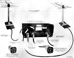
AN/APG-4
--94--
AN APG-4
I. FUNCTION
AN/APG-4 is an air-borne electronic low-altitude bomb release device designed to effect automatic release of a missile from an aircraft, directed toward an isolated or semiisolated marine surface vessel. It is complete in itself except for the employment of a radio altimeter (AYD, AN/ABN-1, AN/APN-1) which provides automatic compensation for altitude variation.
After a collision course has been established visually, or by means of a search radar (separately operated), AN/APG-4, within the operating limits of the equipment, evaluates closing rate and altitude to automatically release the bombs at the proper point.
II. DESCRIPTION
The AN/APG-4 consists of:
-
A frequency-modulated transmitter-receiver unit.
-
An altitude compensation switch with controlling relays.
-
Two Yagi antennas (similar to ASB equipment).
The antennas are moulded so as to direct a beamed lobe of radio energy forward and downward from the aircraft. One antenna is used for transmitting the frequency-modulated signals generated in the transmitter; the other antenna is used to receive the returning echo signal from surface targets.
III. MODE OF OPERATION
Figure 2-81 shows a functional block diagram of the AN/APG-4 equipment.
With the aid of the radio altimeter, the aircraft is flown al any height between the altitude range of 10 to too feet. In the transmitter, a frequency-modulated signal is generated and delivered not only to the transmitting antenna but also directly to the receiver. The transmitted signal is beamed by the transmitting antenna ahead to a target and the reflected signal is received on the receiving antenna, from which it is fed to the receiver.
The instantaneous difference between transmitted signal frequency and reflected signal frequency produces in the receiver a third or difference frequency which is a measure of the distance between the aircraft and the target, and the closing rate. This information is resolved in the receiver circuits into voltages proportional to distance and closing rate, with compensation for altitude variation, which, after evaluation by the AN/APG-4, actuate relays at the proper time to operate the bomb release mechanism.
The factors of speed, altitude, and distance are thus automatically obtained by the equipment and evaluated to determine the point at which automatic bomb release takes place. Azimuth information must be obtained by pilot or operator either visually or through the use of airborne radar equipment.
IV. PERFORMANCE CHARACTERISTICS
1. Operating limits.--AN/APG-4 is effective over a range of aircraft speeds of 100 to 300 knots and at altitudes of from 40 to 400 feet.
2. Range lead adjustment.--Provision is
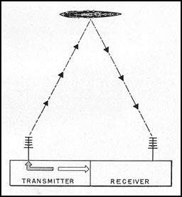
Figure 2-81.--In the APG-4 equipment, frequency-modulated signals are directed toward a target by the directional transmitting antenna. A small portion of the frequency-modulated signal is also fed directly to the receiver. Since a measurable period of time elapses from the time the signal (of a given frequency) was transmitted to the time it is received, the difference in frequency between the returned signal and the new frequency-modulated signal then being generated in the transmitter is resolod into terms of distance.
--95--
made in the equipment for releasing a bomb so that its point of impact may be anywhere from zero to 100 feet ahead of the selected target (skip-bombing application).
3. Computation time.--Because the automatic computation of bomb release time requires only four-tenths of a second, a pilot may engage in extreme evasive action up to a point immediately prior to bomb release.
5. [sic--no #4] Target isolation.--The equipment tracks and releases on the nearest object in view; therefore, it is essential that the target be isolated from objects by a minimum of approximately 150 yards.
NOTE.--The AN/APG-4 will be superseded by the AN/APG-17 and AN/AFG-17-17A. The AN/APG-17A is a low-altitude level-flight frequency-modulated automatic bomb release system using either visual or radar sighting and permitting evasive maneuvers up to point of release. Range of altitude operation is from 40 to 400 feet and the equipment obtains its altitude information from the AN/APN-1 radio altimeter. It requires no operator other than the pilot. Two faired-in parabolic antennas are required. This equipment will supersede the AN/APG-4 due to better aerodynamic characteristics and greater power. The AN/APG-17A will provide for operation up to 800 feet and will be suitable for rocket release. The weight is slightly less than the AN/APG-4 (5 to 10 pounds estimated).
--96--
AN/APG-5
I. FUNCTION
A. PRIMARY PURPOSE. AN/APG-5 is a lightweight air-borne fire-control radar equipment. It is an automatic ranging equipment which supplies target information to a lead computing sight, as used in the upper and lower gun turrets of aircraft.
II. DESCRIPTION
A. MAIN COMPONENTS. AN/APG-5 consists of the following:
-
A transmitter-receiver unit.
-
A directional antenna.
-
A range unit.
-
Servo amplifier and servo-geared motor unit.
B. MODE OF OPERATION. The transmitter generates pulses of radio-frequency energy which are fed to an antenna having highly directional qualities. The antenna, mounted on the gun turret and rotatable with it, directs the radio-frequency pulses toward a selected target in a 28° beam.
Echo pulses from the target return to the same antenna and are fed to the receiver and range unit. The range unit performs the function of measuring the time intervals between transmitted pulses and received echoes, continuously maintaining a voltage output proportional to the time interval, and therefore to range.
The servo amplifier and its associated servo-geared motor unit converts this voltage output to a sha ft rotation proportional to range, which may, in turn, be fed into a lead computing sight.
The AN/APG-5 is entirely automatic in operation and requires no separate operator. The gunner operates the necessary controls. Using his optical sight, the gunner operates his turret and his guns in such a manner as to visually train his guns on the target. This simultaneously aims the radar antenna at the target. AN/APG-5 then automatically tracks the target in range and will indicate to the gunner that it is feeding range information into his sight. This indication is in the form of a target indicator light which is placed on the sight so that it may be readily observed by the gunner without the need for shifting his view from the target. The gunner then merely keeps his guns trained on the target and fires when at the proper range.
In the event there is more than one target present, the gunner may select a closer or a more distant target by pressing the IN or OUT switch of the target selector, which is mounted on the handle bar control. He can tell when he is on the proper target by noting the relative range as indicated by the reticule separation on the optical sight.
In the event of radar failure, the target indicator will not operate. When this occurs, the gunner can immediately regain manual control. He operates his sight by using the target selector to drive the servo-geared motor unit, which, in turn, drives the range mechanism of the sight. In doing this, he uses the sight as he would if there were no radar equipment installed.
C. PERFORMANCE FACTORS. The AN/APG-5 system will operate in ambients from minus 55° C. to plus 50° C.
The system is capable of automatically tracking aircraft reliably to a minimum distance of 200 yards.
The over-all system error, on the 1,800-yard scale, is less than ± 50 yards.
The system is designed to operate between the limits of 6,000 to 40,000 feet altitude.
--97--
Table of Contents
Previous Part (I)
Next Part (III)


