Chapter 15
COUNTERMEASURES TO THE GERMAN
ACOUSTIC TORPEDO
During the last 20 months of World War II German U-boats made operational use of acoustic torpedoes, which were first employed in September 1943. The
general performance of the torpedo is as follows: It is fired in the normal manner, that is, under gyro control on a collision course. When the torpedo
comes sufficiently close to a noise source, such as the ship's propellers, it hears the noise and "homes" on it, i.e., turns towards the source and
attempts to keep headed towards it until a hit occurs. The torpedo need merely come within homing range of the ship to have a high probability of hitting.
In effect it makes for itself a larger and more circular target than that of an ordinary "straight-run" torpedo. The louder the ship (in the frequency band
received by the torpedo), the greater will be the homing range and consequently the effectiveness of the weapon.
| 15.1.1 |
Types of Countermeasures |
The simplest of the several possible countermeasures to such a torpedo-slowing the target-is suggested by the fact that a ship's sound output increases
rapidly with speed. A ship is so much quieter at 7 knots than at 15 knots that the homing range is only about one-fifth that at the higher speed, and the
effective target size is correspondingly reduced. Slowing considerably increases vulnerability to torpedoes of other types, however. Other means of quieting
the ship's propellers, such as masking them with bubbles, have at best halved the homing range in tests to date.
Slowing the ship is an example of a tactical countermeasure since no new gear is required for its introduction. A materiel countermeasure, on the other
hand, is one which does involve the use of special equipment. Another type of tactical countermeasure is possible if the target ship has sufficient warning
as to when and where the torpedo is fired and if the torpedo's homing range is not too great. A radical maneuver may be made which will keep the ship out of
listening range of the torpedo. This has been called a "step-aside" when used by an antisubmarine vessel attempting to approach the submarine for an attack.
It is useful only when contact has been made at long range and hampers the ship considerably in its attempt to get in to sonar contact.
The third tactical countermeasure is to maintain a speed greater than that of the torpedo and is therefore unavailable to many ships. A torpedo homing on
a target faster than itself will usually be left behind. Its listening sensitivity is limited by its own self noise,40 which in turn increases rapidly with
its speed. Thus some compromise is required between speed and homing range, and an acoustic torpedo will usually be slower than its straight-running counterpart.
The ship speed required to outrun the German torpedo was initially considered to be about 20 knots; this estimate was later raised to 25 knots, but final
information indicated that 20 knots was adequate after all. Continual rumors of a 30-knot modification of the torpedo cast doubts on these figures, however.
In addition to the above tactical countermeasures, there are several possible materiel countermeasures. These usually involve noisemakers [NM's], which
are small devices, yet several times louder than a ship at the frequencies received by the torpedo. The NM's must be placed so as to attract the torpedo on
its initial approach and thereafter prevent its getting into a position to home on the ship. By the end of 1943 escort vessels were equipped to tow one or
two noisemakers about 200 yd astern. Equipment of this type was the standard materiel countermeasure employed during the remainder of World War II.
The evaluation of such countermeasures would be much simplified and shipboard morale much improved if some indication were given when a torpedo has been
successfully countered. Development work was done on several devices to detonate the torpedo before it reached the ship. These included nets, rotating barriers,
explosive streamers, and magnetic fields set up by trailing electric cables. They
--161--
were simplest and most effective when used with towed NM's. However, they were never issued because they were fragile, difficult to handle, uncertain
in effectiveness, and seriously impeded the ship's maneuvering.
A towed NM alone interferes considerably with the antisubmarine vessel's offensive. The towline restricts the maneuverability of the ship, and the
sound generated interferes with sonar and gives the submarine early hydrophone warning. To get around these disadvantages consideration was given to
expendable noisemakers projected from the ship or dropped astern. By 1945 such noisemakers had been produced for masking U. S. submarines from enemy
sound gear, and their practicability as a torpedo countermeasure had been tested. As long as there is danger of a torpedo being fired, an NM must be
projected at least once every 90 sec. This expenditure is feasible only when a submarine is known to be close. It has long been envisaged that the
ultimate countermeasure to acoustic torpedoes would incorporate a detector which would give sufficient warning of an approaching torpedo to investigate
the successful use of expendable NM's. Such a detector is not yet available.
| 15.1.2 |
Scope of Further Discussion |
The bulk of this chapter deals with the evaluation of towed NM's, since this type of countermeasure was of primary importance during World War II. The
effectiveness of such a countermeasure depends on the mode of operation of the torpedo, and, therefore, the discussion deals chronologically with the
evaluation in the light of changing information concerning the nature of the torpedo.
The most important information to be gleaned from operational data is also included. The data are discouraging since in most cases only those torpedoes
which hit ships are detected. In addition it is difficult to decide which torpedoes were acoustically controlled and this makes interpretation of the data
uncertain. It is hoped that these difficulties can eventually be overcome by analysis of German Admiralty records, which should give further information on
the operational effectiveness of Allied noisemakers.
Expendable NM's did not see operational use and will not be discussed further. They must be kept in mind, however, as having possible future usefulness.
Detailed evaluation of tactical countermeasures is also omitted. It is now felt that high speed is the only tactical countermeasure likely to be very
effective, and it can rarely be used.
| 15.2 |
DEVELOPMENT OF TOWED NOISEMAKERS |
| 15.2.1 |
German Introduction of Acoustic Torpedoes |
By early 1943 intelligence information indicated that the Germans had an acoustic torpedo in production and that successful running tests had been
made the previous summer. Accordingly, the Allied study of countermeasures, which had been following along with the development of similar torpedoes,
was put on a high priority. Soon the different possibilities mentioned in the Introduction had all been given some consideration.
An excellent towed NM was already in use for sweeping acoustic mines. This device consists of two steel bars, clamped parallel close together, which
are pulled through the water in the direction perpendicular to the plane containing their axes. The water flowing between them causes the bars to strike
against each other and give off much more acoustic energy than does a ship at all frequencies greater than 1 kc.41 Both Great Britain and the United
States proceeded to modify noisemakers of this type so that they could be towed at an adequate speed (at least 10 knots) and produce good sound output
for a life of several hours. The parallel-bar type of noisemaker has subsequently been in general use by both navies.
By May 1943 the British had information indicating that the German torpedo homed at 20 knots with a minimum turning radius of about 100 yd and that
its homing range might be as great as 1000 yd. They also suggested that the torpedo might be "forward-listening," in other words, that the hydrophones
might be very insensitive to any sound approaching from near the torpedo's stern (in order to reduce the self noise from its propellers).
From this information the British concluded that two NM's should be towed 200 yd astern and separated by about 100 yd. As will be shown later, the
--162--
torpedo is very likely to overtake a towed noisemaker from the rear at some time in its gyrations and to pass over the NM and head toward the ship.
With a forward-listening torpedo there might be considerable danger that the torpedo would escape from a single NM at this time, hearing and overtaking
the ship while keeping the NM in the insensitive arc astern. If, however, as it left one NM behind, the torpedo found another on its beam, this second NM
could be relied on to take control. The simplest way to get this protection was to tow two noisemakers abreast, sufficiently separated to assure that whenever
the ship was ahead of the torpedo there was also an NM within 110 degrees of the torpedo's bow. To provide separation the British began developing a diverter
with the necessary rudders to tow an NM fastened below it at the required distance out of the ship's wake. They already had a parallel-pipe noisemaker with a
sound output 20 db over that of a ship and an endurance of 25 hr at 12 knots. The name FOXER was given to the complete set of this noisemaking gear, including
two NM's, two diverters, and the towing hawsers.
In the United States a parallel-bar noisemaker designated FXR was in production by July 1943. Preliminary theoretical studies had been made of the behavior
of an acoustic torpedo under the influence of a ship and an FXR 500 ft astern. The tacit assumption was made that the torpedo could listen equally well in all
directions. It was concluded that one NM could maintain control of the torpedo once the torpedo had reached it and that the only danger arose from torpedoes
fired from directly ahead which were drawn in to, or very close to, the ship while homing on the FXR.42
During the summer sonic prisoner of war information43
(later proved false) indicated that the hydrophones were along the torpedo's sides. This tended to substantiate the all-around listening theory and the
belief in the adequacy of one noisemaker.
Prisoners of war also stated that the torpedo was for use primarily against escort vessels, enabling the U-boat to disrupt a convoy's defenses. This
possibility had not occurred to the Allies, probably because the screening vessels had never been a major target,44 and because it was considered unlikely
that the self noise could be reduced enough to allow a speed as great as 20 knots. Escort vessels now seemed the most logical targets for an acoustic torpedo,
however. Their speed, maneuverability, small size, and the frequency with which they were bearing down on the U-boat and thus presenting a very small bow
aspect, all tended to make escorts very poor targets for ordinary torpedoes. With a homing torpedo, however, all these disadvantages were cancelled; the
higher speed gave a louder, and therefore larger target, while bow shots were possibly preferable to beam ones.
More effort was, therefore, expended on parallel-bar NM's suitable for higher speeds. The British ran into more difficulties with their cumbersome diverters,
but the possibility of getting such gear used successfully seemed greater when it was to be handled by naval crews than by merchant vessel crews.
Such was the situation when the Germans were first ready to use their acoustic torpedo against the Allies. It was introduced on September 20-22, 1943, during
the first full-scale North Atlantic operation since May, namely the wolf-pack attack on Convoys ONS 18 and ON 202. Three escorts and six merchant ships were sunk
and an escort damaged; acoustic torpedoes accounted at least for the damaged escort and two of the other escorts. In contrast a German War Order claimed 12 escorts
sunk, 3 damaged, and 9 merchant ships sunk, which indicates a high expenditure of torpedoes. Nevertheless, the torpedo proved itself a threat which might have been
much more effective had the enemy been able to get more than two U-boats in contact with the convoy at one time. As it was, the potentialities of the torpedo caused
the Allies extremely grave concern.
On September 23 the Admiralty issued a comprehensive appreciation of the use of the German acoustic torpedo. This included a review of the information
available on the torpedo, a preliminary analysis of the first attacks (1 and 2 days old), tactical countermeasures, and a status report on FOXER, which was
to be issued although it was hard to stream, short in endurance, hampering to maneuvers, and difficult to produce.
In the United States an extensive study of the countermeasure problem was begun. On the one hand reports on the torpedo's characteristics were
--163--
collected and evaluated; on the other, development of a variety of noisemaking gadgets was undertaken. One of the early decisions was to discourage the
development of impulsive noise sources with bursts less frequent than about 20 per second; these included rapid machine gun fire into the water and the grenade
noisemaker composed of a series of explosive caps. It was felt that the torpedo probably would not respond to such a source, whereas if it did, a relatively
steady source such as a ship would be able to override it even when providing a much weaker rms (or average) signal. Such discrimination would occur with the
time constants which were most natural for a torpedo's amplifying and control circuits. This would not only be a good anti-countermeasure device but would also
(and more important) discriminate against the irregular peaks which are among the most undesirable features of a torpedo's background noise.
It soon became apparent, however, that a reliable evaluation of the performance of any particular countermeasure required a detailed understanding of just
how the torpedo functioned. The two different assumptions which have been mentioned-forward-listening and all-around listening-lead to quite different NM
arrangements. A careful analysis of the probable behavior of acoustic torpedoes was, therefore, undertaken. Its salient features are outlined in the following
sections.
| 15.2.2 |
Torpedo Trajectory Analysis |
The primary aim of a study of torpedo behavior is to determine the path which the torpedo follows its trajectory-under the conditions that are of
interest. In order to do this a means must be developed for rapidly predicting a torpedo's behavior in the presence of a particular NM system and under
a particular set of assumptions as to an unpleasantly large number of torpedo characteristics, as will be apparent from the following discussion. Of
obvious importance is the torpedo speed. It determines the ship speed necessary to outrun the torpedo. The torpedo trajectory can be expressed as a
function of the ratio of the ship's speed to that of the torpedo.
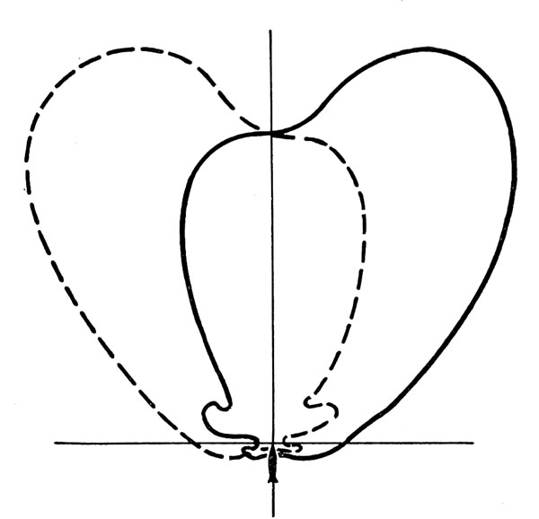
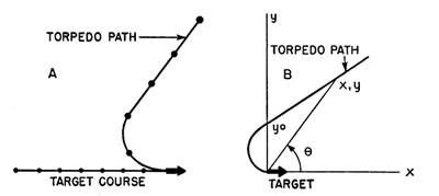 |
FIGURE 1. Typical tractrix. (A) In true space. (B) In relative space. |
Under the influence of a single noise source the torpedo can be assumed (for a first approximation) to attempt always to steer towards the source.
This results in a straight path when the target is stationary, e.g., an expendable NM. With the target at constant speed on a straight course the pursuit
curve is a tractrix. Except for an adjustment in scale any tractrix is like that shown in Figure 1. With an (x,y) coordinate system centered on the target
and the target heading in the positive x direction, the relative trajectory is given by equation (1).
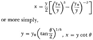 |
Equation (1) |
| where |
k = ratio of target speed to torpedo speed, |
| y = distance at which the torpedo first passes abeam of the target, |
| θ = torpedo's bearing relative to the target. |
In stationary coordinates whose origin is the target's position at the time the torpedo is first abeam of it (at distance y0) the target's positions are given by equation (2), the tractrix, by equation (3).
 |
Equation (2) |
| |
 |
Equation (3) |
When dealing with targets moving together, such as a ship and towed noisemakers, it is simplest to draw trajectories relative to this moving system. For each
 |
FIGURE 2. Course of torpedo when circling. (A) Fixed coordinates. (B) Relative coordinates
(speed ratio = k = ½ ship motion →). |
--164--
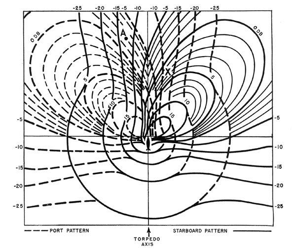 |
FIGURE 3. Typical sensitivity pattern. |
value of k that it is desired to consider, a template sheet can be prepared, covered with a family of tractrices - calculated from equation
(1) - so that by interpolation a pursuit course can be drawn from any point in to the center. For any specific problem the trajectories can be traced
from these templates.
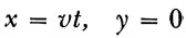
A torpedo cannot always follow a tractrix, however, because its minimum turning radius may prevent it from making the sharp turn required. If the torpedo
turns as sharply as possible when trying to get headed towards a noise source,45 its path in relative space will be a cycloid rather than a tractrix. A typical
cycloid is shown in Figure 2. Templates can be drawn for cycloids in the same way as for tractrices as an aid in drawing the relative
diagrams.
The behavior of the torpedo depends upon acoustical and electronic features as well as speed and turning radius. In the fall of 1943 the exact characteristics
of the German torpedo were unknown, but it was considered probable that a listening system was employed46 and that the following general scheme of operation was used in order to determine from which side of the torpedo
the sound arrived.
--165--
The rudder is controlled by the ratio of the voltages in two electric channels. If a steady sound source is moved about the torpedo at a constant range,
the voltage in the port channel is much greater when the source is within some range of bearings on the torpedo's port side than when anywhere on the starboard
side. Similarly, the starboard channel is most sensitive to signals from the starboard side.
In determining a trajectory, it is necessary to find out for each torpedo position just what are the relative voltages in each channel due to each noise
source. To facilitate this another set of templates are drawn, one for each assumed sensitivity pattern. Each template is a transparent geographic plot to be
centered on the torpedo position with the torpedo axis marked. By one curve it shows the locus of all points at which a standard (arbitrary) noise source would
create a given voltage in the port channel and, by another, the same for starboard channel. Parallel lobes are drawn corresponding to sources each an integer
number of decibels louder or softer than the standard. A typical sensitivity pattern of this sort is shown in Figure 3.
A standard noise source at point X in Figure 3 would give a signal of -12 db in the port channel and +2 db in the starboard. If, at the same time, a source
10 db louder than the standard (for example) is present at point A, it would give a signal of 8 db in the port channel, and -3 db in the starboard. In order to
obtain the total voltage in each channel with both present, the square root of the sum of the squares of the individual contributions is taken. This method
should be sufficiently accurate unless a source is very intermittent, e.g., a grenade exploding only ten times a second.
In constructing these templates it is assumed that the sound pressure is inversely proportional to the range from the source (6 db less per distance doubled).
This is only an average value of the attenuation found in experiments, but the effects of considerable fluctuations can usually be shown to be negligible. The
ranges involved at critical times are too small to allow the linear absorption of sound in open water to become important. However, there is evidence of
considerable attenuation in the ship's wake, about 2 db per foot at 24 kc.47
The simplest sensitivity pattern is a circular one.
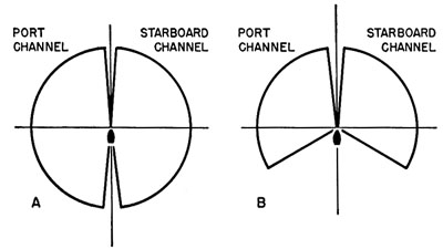 |
FIGURE 4. Simplified sensitivity patterns. (A) Circular pattern. (B) Modified circular pattern. |
The template curves for each channel are semicircles on each side of the torpedo axis, as shown in Figure 4A. Dead zones of no differential arc assumed
to be present, but negligibly small, ahead and astern of the torpedo.48
To break away from all-around listening it may be assumed that there is a wide angle of zero sensitivity astern, leaving the lobes as shown in Figure 4B.
A more realistic picture may be obtained by using another mathematical approximation which recognizes that the response of any hydrophone system will change
smoothly with angle. If θ is the angle off the torpedo's bow, the contours of equal sensitivity can be expressed by cos (Nθ). The
sensitivity will then be a maximum ahead (except for a negligible dead angle) and will decrease gradually as θ increases, becoming zero for all
θ's greater than π/2N. A number of such patterns are shown in Figure 5. For N = 12 there is some listening at all angles except dead astern, whereas for
N = 1 there is no response anywhere abaft the beam.
In an actual torpedo each channel may have its own set of one or more hydrophones directed toward one side. Alternatively the channels may be connected
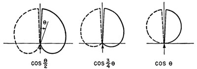 |
FIGURE 5. Cos (Nθ) sensitivity patterns. |
--166--
through phasing circuits to the same, or partially the same, group of hydrophones all facing forward. Either system would lead to the same kind of pattern.
It is reasonable to expect that if an effort is made towards forward-listening, the maximum lobe for each channel would probably be rather broad and centered
between 20 and 60 degrees off the bow. It is difficult to secure a rear response of either channel less than about 30 db below the maximum, no matter what the
direction of the noise. There can be a rather large angle astern where a loud source would bring about approximately the same voltage in each channel. Accordingly
a template can be drawn for a "practical" pattern having a maximum sensitivity 45 degrees off the bow and sensitivity 30 db lower in both channels throughout a
100-degree arc astern.49
This pattern is, in fact, shown in Figure 3. The pattern could be made sharper and the fore-aft discrimination greater if the frequency
of maximum sensitivity were over 40 kc. This, however, would reduce the homing range as a result of the absorption of sound in open water, which becomes
appreciable at such frequencies.
The rudder position should depend on the decibel differential between the two channels, that is, on the ratio of their voltages. Any control involving the
absolute magnitudes of the voltages could not handle the widely different signal strengths to be expected. By the use of the templates and a curve expressing
in decibel units the square root of the sum of the squares relationship, the signals in the two channels can be found in decibels above the same standard; these
values can then be subtracted to give the differential.
The most plausible simple assumption as to the way in which rudder position depends on the differential is a "flip-flop" type of control in which the rudder
is thrown hard over whenever one channel has a given excess (say 3 db or more) and stays over until the other channel has the required excess. This flip-flop
control appears necessary for a forward-listening type of torpedo on the basis of the following argument.
Most torpedoes approaching from forward angles will miss a ship (with no noisemakers) on the first pass because they cannot turn sharply enough to stay on a
tractrix and possibly because the principal target may actually be collapsing bubbles in the wake somewhat astern of the propellers. Having passed the ship's
stern, many of these torpedoes will have the ship in the sector on their own stern where they can get no differential or even any signal over background. If,
with no differential, the torpedo straightens out or returns to its original gyro course, it will never hear the ship again and be lost astern. On the other
hand, with flip-flop control the missile will continue circling until it again hears the target. The same would happen about a single NM towed astern.
Admittedly the torpedo would stay on its tractrix with less weave if on loss of differential it straightened out or, preferably, had "graduated control,"
that is, if the amount of rudder depended on the differential and thus on the bearing of the target off the bow. However, even with flip-flop control the
weave should not be more than 10-20 degrees, and improvement in this would not compensate for the failure of so many bow shots.
The critical differential, designated by D, may reasonably be assumed to be 3 db. With a lower value there would be too much danger of undesirable rudder
actuations. These might result from minor lobes in the sensitivity pattern astern, from fluctuations in the background noise, or from fluctuations in the
transmission of the ship's sound. With these limitations, D should be as small as possible, because the larger D, the less the torpedo's homing range. As a
torpedo approaches a ship from a distance under gyro control, background sound will initially predominate, causing approximately the same voltage in each
channel. If the bearing to the ship is near the angle of maximum sensitivity for one channel, the voltage in that channel will increase as the ship is
approached. The torpedo will turn towards the ship when the voltage in that channel due to the ship plus background is D db greater than that in the other
channel, which is due to background plus a negligible contribution from the ship. If a greater D is required, the torpedo must approach closer on gyro before
the ship noise can overcome background.
The maximum range at which a given ship flips the rudder changes greatly with the bearing θ of the ship off the torpedo's bow. The range is zero with the
ship either dead ahead or (probably) in a large sector astern, that is, with θ's at which the sensitivity patterns for the two channels differ by less than D
db. At other θ's the range depends chiefly upon the sensitivity patterns. For any choice of sensitivity pattern,
--167--
of D,50 and of ship intensity over background,
a so-called steering pattern can be drawn plotting the rudder actuation range against θ. Such curves are useful only when no NM is present.
The maximum of either lobe of a steering pattern gives the maximum range at which a ship can direct the torpedo. The value of this range depends on the
noise output of the ship and on how well the torpedo's background noise has been suppressed. Neither of these quantities can be determined very accurately.
Even for a given torpedo and a specific class and speed of ship there would be enough variation in ship output and in transmission conditions to make the
range uncertain within a factor of three. It would obviously be unwise to base a countermeasure on an arbitrary actuation range.51
It is now possible to consider briefly the trajectories for which the torpedo was primarily designed, namely those against an unsuspecting ship. Assuming
the torpedo to be a modification of the German electric G7e, the firing range was probably not over 6000 yd. Ranges between 1000 and 4000 yd would be the most
likely. The initial gyro course would be a collision course for the ship, possibly for the ship's stern, in order to get the best chance of coming within
homing range. When the torpedo reaches a point where the ship's noise can overcome background noise (as shown by the ship's stern reaching the appropriate
contour on the steering pattern centered on the torpedo), the missile turns toward the ship. If this happens at short enough range, the torpedo might hit
the ship before turning far enough to head at the stern, as shown by trajectory A, Figure 6. Alternatively, assuming flip-flop control, the torpedo will turn
until the screws have passed through the dead angle of small differential on its bow and have reached the opposite lobe of the steering pattern where the
other channel has a D-db excess, causing the rudder to flip. With a forward-listening pattern and mechanical time constants of the order of 1/10 sec, the
course reversal should occur with the target less than 10 degrees off the bow. By repetition of this procedure the torpedo follows a tractrix towards the
screws with a small weave. Trajectories marked B in Figure 6 are examples of such tractrices.
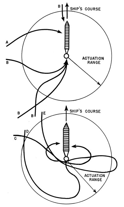 |
FIGURE 6. Trajectories relative to ship. |
If the tractrix approaches from dead ahead, the torpedo may hit the ship before coming abeam the screws. If the tractrix is entered sufficiently far
astern, the torpedo will follow it all the way in, making a hit on the ship's stern. In the intermediate cases, including most shots fired from forward
of the beam, the torpedo is not able to keep headed for the screws because the radius of curvature of the tractrix becomes less than the torpedo's minimum
turning radius. (In the (x,y) coordinates of Figure 1 relative to the source the loci of such points are two circles
tangent to the
--168--
x-axis at the origin and of radius ½KR, where R is the turning radius of the torpedo.) The torpedo is forced to lose ground astern,
usually missing the ship on the first pass. Even though the ship may now be in the dead zone astern of the torpedo, the flip-flop control will cause the missile
to continue circling forward. It may hit the ship's side before it has circled far enough to be headed at the screws, as in trajectory C,
Figure 6. Otherwise it will make another pass at the screws, usually on a rear tractrix leading to a stern hit, as in trajectory
D. In all cases a hit occurs on at most the third pass, as in trajectory E. Any trajectory can, like those of Figure 6,
be drawn relative to the ship by tracing from the appropriate tractrix and cycloid templates.
| 15.2.3 |
Theoretical Trajectories and Noisemakers |
Next to be considered are the trajectories which arise when a single noisemaker E db louder than the ship is towed under the wake about 200 yd
astern. The submarine's firing procedure would be the same as for the ship alone, but the torpedo would get on a tractrix towards the noisemaker at ranges
of a mile or more, if E is 12 db or more. Thus any torpedo in working order is drawn into the system. The ship's sound cannot influence the torpedo
except within about 50 yd of the screws, as long as the NM is on its forward bearing. Thus the paths to the NM are similar to those to a ship by itself.
A direct hit occurs when the torpedo is drawn into the ship while steering towards the NM. Such hits result from tractrices which happen to go through the
ship. These hits are independent of the NM strength or distance astern. To have a good chance of making such a hit the firing submarine must be directly ahead
of the ship, not more than about 3 degrees off the bow. Conversely, the ship can be made safe from them by never heading directly at the submarine.52
If the NM is too weak or too far astern, a forward-listening torpedo fired from about 10-20 degrees off the ship's bow may make an indirect hit. This occurs
when the tractrix comes close enough to the ship that the torpedo is forced to circle out of the tractrix across behind the ship's stern and then to pursue the
ship to a stern hit keeping the NM in the dead angle astern. Path A in Figure 7 shows a trajectory which might lead to an indirect
hit. For the following explanation assume that the torpedo is weaving towards the NM past the ship's port side. While turning to the left in the weave, the left
channel may receive a signal from the ship which is within D db of that received in the right channel from the NM. (This is determined by employing the
sensitivity pattern template as described in Section 15.2.2.) If, as a result of the proximity of the screws, this occurs even when
the NM is at the angle of maximum sensitivity for the right channel, the differential D is never obtained, and the torpedo continues to circle left as
shown in Figure 7. During the turn the NM's bearing off the torpedo's bow increases steadily through angles of decreasing sensitivity.
Meanwhile in the dangerous cases the bearings to the screws (on the other side) increase less rapidly and the range to the ship decreases, all tending to keep
the torpedo circling. This condition continues if the torpedo has space in which to turn sufficiently (about 90 degrees) before crossing the wake. Eventually
it will be heading towards the screws with the NM in its dead angle astern and will be guided in to a stern hit. If the
 |
FIGURE 7. Typical trajectories relative to a 12-kt ship with single towed noisemaker. |
--169--
tractrix is too close to the ship, however, as in Path A' of Figure 7, the bearing to the ship increases rapidly at about the time
of crossing the wake and the NM regains control.
Thus there may be a dangerous group of tractrices close enough to the ship for the latter to deflect a torpedo but far enough away to allow it sufficient
circling space. The danger of indirect hits can be eliminated by making the NM sufficiently loud to prevent the torpedo leaving any tractrix which is far enough
from the ship to give circling room. Any reduction in torpedo turning circle therefore obviously increases the danger from such shots. For the cos
(½θ) patterns or "practical" sensitivity patterns, the E required of an NM 200 yd astern is about 10 db.
Torpedoes which have made neither direct nor indirect hits continue to the NM, as shown in Figure 7. As with a ship alone, some
approach the NM from the rear, making a so-called stern chase. The others pass astern of it, circling forward with minimum turning radius. These shots circle
across in front of the NM and continue circling, falling way behind the NM and entering a stern chase. All trajectories lead to a stern chase after at the most
four passes at the NM. By employing various sensitivity patterns, it can be shown that during this preliminary weaving about the NM the ship cannot capture the
torpedo provided the NM is as much as 200 yd astern and is able to hold the torpedo after a stern chase.
The success of a single noisemaker arrangement thus depends on its ability to prevent a torpedo which has just passed over it on a stern chase from continuing
on to hit the ship. The most critical factor is the torpedo's sensitivity pattern.53 There is no problem if the torpedo can hear about equally well in all
directions (as was assumed in the earliest United States studies) since the NM, being louder and closer, is certain to be heard over the ship and to make the
torpedo circle to the rear, where it would start another futile stern chase. No matter how loud the NM, it cannot be depended upon to counter a "mathematical"
pattern with a sector astern in which the sensitivity is zero (no listening whatsoever), such as that in Figure 4B. The NM is likely to fall into the dead zone
and stay there while the ship noise guides the torpedo to a hit.
The cos (½θ) pattern, however, with the sensitivity greater than zero everywhere but right astern, is countered by an NM louder than the
ship by 10 db or more. In this case attenuation of the ship's noise in the wake is sometimes needed to cause the torpedo to turn sufficiently for the NM to
regain control. With an estimated 0.1 db per foot for the attenuation there is no chance that a torpedo in the wake and back near the NM could hear the ship.
This protection is not diminished if the NM should happen to be to one side of the wake rather than underneath it.
The more realistic practical sensitivity pattern gives new assurance of the value of a single NM. Having passed over a sufficiently loud NM on a stern chase,
a torpedo with a practical pattern receives so much signal in both channels from the NM that the additional ship sound in one channel cannot provide the necessary
differential to flip the rudder. With flip-flop control the torpedo stays in the circle it happened to be in as it crossed the NM until it falls way behind. For
an NM towed 570 ft astern an output of 12 db above the ship can be shown to be adequate. The required output decreases slightly with increased ship speed because
the torpedo's distance of closest approach to the ship is increased.
On the basis of early recommendations FXR was being prepared during the fall of 1943 with 200 yd of cable. The cable sag resulted in a towing distance of 570
ft. The completed trajectory study, made following the above outline, revealed no reason for changing this. A longer tow would require a higher output to prevent
indirect hits and would increase the difficulties of handling the gear. A shorter tow would require a higher output to prevent stern chase hits. It would have
been nice to tow the NM beyond the homing radius of the torpedo on the ship. This was precluded, however, by the uncertainty of this radius and by the greater
NM output required to prevent indirect hits if, as is likely, the radius is over 200 yd. The FXR had to be "depressed" below the bottom of the wake so that its
sound would not be muffled in any direction. There was, however, no harm in its towing somewhat to one side of the wake while still maintaining its depth.
Consideration was given to a noisemaker fixed with respect to the ship but on some bearing other than astern. These other positions, which might have been
accomplished by concentrated machine gun fire, seemed to be inferior. The chance of direct hits increased since the ship cut across more tractrices.
--170--
 |
FIGURE 8. Typical trajectories relative to a 16- to 18-kt ship with two towed noisemakers. Similar trajectories
from starboard side. |
For safety from indirect hits it was necessary to keep the NM within 300 yd of the screws. Most important, the ship was in a better position to capture
the torpedo as it circled back from the NM. Finally, the sonar interference would be increased.
Trajectory analysis confirmed the conclusion that two NM's towed abreast gave a more certain countermeasure than a single FXR. The advantage of the British
double FOXER lay in its elimination of practically all the ambiguity with regard to stern chases. Even a torpedo with zero sensitivity abaft the beam (e.g., the
cos θ pattern in Figure 5) could be relied upon, after it has passed over one NM, to be drawn to the other before getting too
close to the ship, as shown in Figure 8. During the initial approach the FOXER system is equivalent to one NM with the same total output.
The torpedo is either on a tractrix toward one of the NM's or towards the "acoustic center of gravity" between them. Thus the chance of a direct or indirect hit
is essentially the same for the double FOXER as for a louder single FXR.
Highest priority was given to the development of adequate diverters. However, as the British were finding out, the production and handling difficulties
seemed to be extremely great with FOXER. Since most of the evidence indicated the adequacy of a single NM, the decision was made by the United States to issue
FXR. Emphasis was placed, however, on the importance of examining each bit of new evidence to make sure that this decision was not invalidated.
| 15.2.4 |
Detailed Intelligence Concerning the German Torpedo |
As the ideas described above were being worked out in detail during the fall of 1943, further information was accumulated on the operation of the German
torpedo. In mid-October a detailed and apparently accurate description of the T-4 acoustic torpedo was obtained from a prisoner of war [P/W] whose last cruise
had started on July 20 with three T-4's aboard. He also reported that an improved model, the T-5, was expected for operational use in August. The T-4 was a
modification of the electric G7e torpedo slowed to 20 knots and with larger rudders to give it a 90-m turning radius. A liquid-filled plastic nose enclosed two
forward-facing hydrophones. In a pre-installation test ("Spatz" test) the rudder was seen to have three positions, hard over on each side and occasionally
central, as a noise source was moved about the nose. A switch was to be set on either "WS" or "NS" at the time of firing. This switch had an undecipherable
effect on the acoustic rudder control, which did not become clear until much later.
Another prisoner of war who had observed running tests of the torpedo in the Baltic confirmed the general features of our trajectories, but added a noticeable
weave. This tended to confirm the belief that flip-flop control was used.
With the prisoner of war's description of the T-4 nose as a starting point, arrangements were made to reconstruct the hydrophones in order to obtain their
sensitivity pattern. By December preliminary results indicated that the T-4 had velocity hydrophones connected by phasing circuits and sensitive at about 5 kc.
The sensitivity pattern would only be about 25
 |
FIGURE 9. Sensitivity pattern of reconstructed T-4 hydrophone system. |
--171--
db down astern. All this was welcome news, tending to confirm the practical pattern, though complete measurements were not made until somewhat later.
All was not rosy, however. Measurements were made with equipment which immediately broke down permanently; these tentatively indicated that the ship's
own sound was not attenuated in its wake at frequencies below 10 kc. Thus the wake could not be depended upon to turn the torpedo after a stern chase. Full
reliance had to be placed on the sensitivity's not being more than 30 db down astern.54
Scattered information was indicating that the T-5 was in use and that it had a speed of 24½ knots. This increased the importance of trajectories
involving low-speed ratios and also increased interest in how self noise had been reduced. One of the more fantastic reports claimed that for acoustic
insulation and extra explosive power much of the torpedo had been stuffed with guncotton! There seemed to be two models of T-5, one with a round plastic
nose like the T-4 and the other with a flat nose. Imbedded in this flat metallic surface were four parallel laminated bars 10 by 2½ cm, their long
dimensions vertical. These were thought to be the surfaces of four magnetostriction hydrophones. It seemed likely, however, that there was a phasing system
between the hydrophones. Their spacing indicated a peak response at about 12½ kc.
There was definite evidence of a magnetic attachment to the T-4's pendulum-type inertia pistol. Several ships had reported explosions in their wakes which
were ascribed to malfunctioning of the inertia pistol. Prisoners of war claimed that this had been corrected. The magnetic feature increased slightly the chance
of a direct hit and, more important, allowed the depth setting to be as much as 10 ft below the keel. This lower depth should have considerably decreased both
the chance of broaching and the self noise. In addition, explosions beneath the ship's keel would be much more damaging than at the side of the hull. Thought
was given to creating a magnetic field about the FXR to detonate the torpedo.
In late January a complete experimental sensitivity pattern was obtained from the reconstructed T-4 nose. It seemed likely that the round-nosed T-5 possessed
this same pattern. It conformed to the assumed practical pattern in that each channel had its maximum sensitivity 25 degrees on its own side of the bow and its
sensitivity at no angle dropped more than 28 db below this maximum. However, each channel had a prominent secondary lobe at about 60 degrees on the opposite bow,
which even with the best adjustment could not be brought more than 2 db below the main lobe of the other channel. At all bearings greater than 60 degrees the
patterns for the two channels remained within 7 db of each other. They crossed over each other in a quite random fashion, as shown in Figure
9. The differential D required for steering would have to be 7 db to prevent false or confused steering, e.g., turning to port when the target was
about 110 degrees off the starboard bow. Nevertheless it was thought possible that in order to get a greater homing range the enemy might have chosen D = 3
db, counting on the low sensitivity astern to prevent confusion by hiding the ship's noise in the background. Whatever the D, only a source between 5
degrees and 60 degrees off the bow could be certain to flip the rudder in the correct direction.
This pattern improved the stern chase situation but increased the danger of an indirect hit. The lower fore-aft discrimination and the likelihood of a
greater D made it more difficult than with the practical pattern for the ship to take over the torpedo after a stern chase. On the other hand, a louder
NM was required to prevent the ship from attracting a torpedo out of a nearby tractrix. If this torpedo circled far enough for the NM to be more than 60 degrees
off its bow, it would continue circling no matter how poorly it received the ship's sound. Usually when it got headed toward the screws it would be in a position
to go in for an indirect hit. A directive was issued to the effect that any U-boat should be kept more than 20 degrees off the ship's bow. By forcing the
tractrices farther from the ship this procedure would eliminate most indirect hits as well as all direct ones.
By January 1944 FXR Mk 2 (suitable for speeds from 12 to 19 knots) was getting into general use
--172--
 |
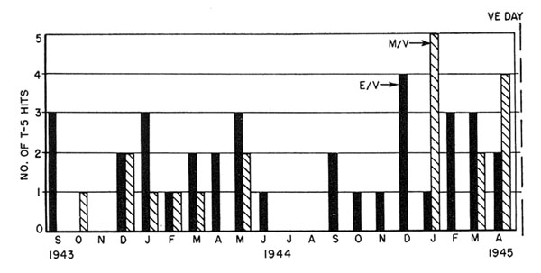
FIGURE 10. Number of hits by German acoustic torpedoes, by months (escort vessels, solid; merchant ships,
crosshatched). |
aboard the larger escort vessels. For lower speeds FXR Mk 3 was being issued to smaller craft. The chief operational difficulties with FXR Mk 2 arose
from the limits imposed upon the antisubmarine vessel's speed and from the depressor (employed to keep the NM below the wake). There were also conflicting
reports as to whether the production models had the specified 12- to 15-db excess in output over the ship. A safety factor of several decibels was certainly
desirable. With much trial and error a 30-inch parallel pipe NM was developed which could be towed at any speed from 8 to 25 knots. It was depressed by a 90-1b
weight called a "minnow." Its output was steadier than that of FXR Mk 2 and was, at 5 kc, 20 to 25 db above the average destroyer escort [DE]; this compared
favorably with the Canadian CAT gear and the components of the British FOXER.
Meanwhile, care was taken to investigate all torpedoings in an effort to determine the part played by T-5's. Figure 10 records for each month the number of
incidents which were designated as probable T-5 hits on the basis of intelligence available before the German surrender. (Complete German records are still not
available.) The importance of towing NM's in dangerous regions was emphasized by the high proportion of escort incidents (7 out of 14 through May 1944) in
which the presence of the U-boat was unsuspected until the range was less than 2500 yd. In these cases no other countermeasure could have been effective. The
sudden burst of antisubmarine ships hit in May 1944 included one case with FXR Mk 2 being towed. The newly developed gear was soon issued and was designated
FXR Mk 4.
In the spring of 1944 a copy of a T-5 firing table was recovered from a U-boat scuttled off India. By substitution into firing triangle relationships the
torpedo's speed was confirmed to be 24½ knots, at least on the initial gyro run. Investigation of the minimum firing ranges (tabulated as a function of
the target's firing course and speed) revealed that the torpedo had a 500-m enabling run, that is, it was set so that the hydrophones could not control the
steering until 30 sec after firing. This was to help prevent the torpedo from homing on the U-boat. The minimum firing range was specified so that after this
500 in the screws would still be at least 200 m ahead; then there was no chance of the forward-looking lobes not hearing the ship.
Although information concerning the torpedo was thus growing steadily, it was still rather fragmentary and unsatisfactory in the spring of 1944. This was
soon to be changed.
| 15.2.5 |
Studies of Captured T-5's |
On June 5, 1944, USS Guadalcanal and escorts captured U-505 with two round-nosed T-5's aboard. The first examination of these torpedoes showed that inside
each plastic nose there were not only two hydrophones and some liquid but also a rubber horn structure directing each hydrophone 30 degrees off the how. Each
hydrophone governed a channel without phasing. The maximum sensitivity of the whole system was at about 27½ kc, considerably higher than had been thought.
This higher frequency was all for the good since NM output had been found to drop off less rapidly with increasing frequency than did ship noise. Thus FXR Mk 4
was about 30 db over a DE at 27½ kc.
 |
FIGURE 11. Measured sensitivity pattern for captured round-nosed T-5, from U-505. |
--173--
By August measurements of the sensitivity pattern revealed a more unpleasant surprise. The response astern was 42 db below the maximum! It followed that
there was some chance of stern hits with FXR Mk 4, especially since D, the differential needed to flip the rudder, seemed to be only 2 db. On the other
hand, the patterns for the two channels, shown in Figure 11, were well separated (by about 12 db) between the angles of 20 degrees and 125 degrees off the
torpedo's bow. This together with the low D and high NM excess eliminated the danger of indirect hits. In fact there were no indirect hit trajectories
even with an NM 400 yd astern. Since the longer tow gave better protection from stern chases, adding more cable would have been recommended, had actual running
tests with the T-5's not been expected very soon.
Such tests were particularly necessary because of a new complication which was discovered. The torpedo was found to have a common amplifier into which the
two channels were switched alternately 108 times a second. If the signals were equal there would be no 108-cycle component in the output. Otherwise the phase
of this component indicated which signal predominated. Trouble arose from the fact that FXR Mk 4 pipes struck together with a frequency from 90 to 115 cycles.
What was the torpedo response to a signal with this modulation? The answer was complicated by the effect of the automatic volume control [AVC].
Some questions were, however, definitely answered by inspection of the torpedoes. The meaning of the "WS" and "NS" settings had been pretty well deduced from
prisoner-of-war information. Now there was confirmation. WS was set on a torpedo being fired from within 90 degrees of the target's bow; this required that when
differential was lost the torpedo would continue in its minimum turning circle-that is, flip-flop control. NS was used on rear shots and made the torpedo return
to its original gyro course after receiving no differential for several seconds; when differential D was again received the rudder would again go over.
The reason for having both settings seems to lie in the fear that the torpedo, as it approaches a ship from a distance, might start circling as a result of
a temporary increase in noise level but before it could receive a steady signal from the ship. This was acceptable on forward shots since the ship's motion was
likely to close the range to where homing could start and since flip-flop control was needed if the torpedo should miss the stern on its first pass. On stern
shots the flip-flop was not needed because the torpedo could stay on its tractrix. Resuming gyro control after a temporary signal was likely to bring it into
homing range of the retreating ship, whereas circling would leave it hopelessly behind.
A consequence of this control system was that even if WS shots were successfully prevented from making stern chase hits, there might be danger of such hits
by torpedoes fired on NS from within 30 degrees of the ship's stern. These NS trajectories on passing over the NM into a region of no differential would take up
a gyro course which would take them towards the ship to a position from which the screws could guide them in to hit. An NS torpedo fired from farther off the
stern would return to a gyro course from which it could never hear the ship or, when it did, it would turn far enough to stern to be recaptured by NM.
Preliminary running tests with the torpedoes revealed a turning radius of 80 yd and a speed of 22 knots on turns and confirmed 24½ knots as the speed
on gyro control.
During October, one year after the first intensive countermeasure studies, detailed observations were made on 20 acoustic runs with the T-5's apparently in
proper operating condition. FXR Mk 4 provided good protection. FXR Mk 2 proved equally effective except on one run during which its output was erratic. The
explanation of this good news lay in the very large weave with which the torpedoes approached these NM's. The torpedo's beam was often presented to the NM
before the rudder flipped to carry the missile into the next phase of the weave. When the ship speed was 15 knots or over, the torpedo was not able to overtake
the NM but weaved back and forth behind it. With a slower target the T-5 was able to circle in ahead of the NM occasionally, but always at such an angle that
the NM continued to control it, at least until it had fallen behind the NM again. There were no passes directly over the NM. Most runs were on NS with the
gyro course parallel to the ship in order to have conditions most favorable for a stern chase hit. Even this did not cause trouble. The ship's wake was so
narrow compared with the weave amplitude that it had no effect. No feature of the trajectories could be correlated with the NM's striking frequency, although
in one case there were less than 2 cycles between the striking and the torpedo-switching frequencies.
--174--
The large weave increased the angle off the target's bow from which a torpedo might be fired and still make a direct hit. A torpedo fired 11 degrees
off the bow made such a hit, but three shots from about 20 degrees missed by 100 ft or more. It seemed that the existing doctrine (a precaution against the
now nonexistent indirect hits) of keeping the U-boat more than 20 degrees off the ship's bow allowed a sufficient margin of safety against these direct hits.
A statistical analysis of the weaving paths verified the rule of 20 degrees. Because the weave amplitude increased as the torpedo approached the NM, it was
found that shortening the FXR towing distance from 200 yd would markedly increase the danger of direct hits. On the other hand, using a 400-yd tow would only
slightly improve matters.
Three runs were made against a 16-knot DE (33db spectrum level above 0.0002 dyne per sq cm at 200 yd) without an NM. The weave on stern approaches was quite
small, the ship seldom getting more than 20 degrees off the torpedo's bow. This was enough, however, to reduce the speed made good to about 19½ knots, so that
a ship making 20 knots or more should be safe from all but shots down the throat.
On one of these runs the torpedo turned toward the ship leaving gyro control at a range of about 1500 yd. Whether or not this was a fluke, the homing range
was definitely over 600 yd, since the torpedo, on being enabled at this range, steered directly for the ship. A 1500-yd homing range would make tactical
countermeasures at speeds of 10-18 knots (step-aside procedures) extremely risky.
On the basis of the performance of FXR Mk 2 in the running tests, development was initiated on an NM with a steady output about that of a good FXR Mk 2, i.e.,
about 20 db over the ship. This gear was to be substituted for Mk 4 whenever the latter's interference with sonar was a serious handicap. However, no satisfactory
design was found.55
During the fall the electronic parts of several flat-nosed T-5's were found in France and sent to England. As had been predicted the hydrophones were combined
by phasing circuits into two channels. The maximum sensitivity was at 27½ kc. The amplifiers were of a different type from those found in U-505's
round-nosed torpedoes. It was established, however, that either the flat-nose or the round-nose hydrophone could be used with either amplifier. Since the
German firing instructions made no distinction between models, it seemed likely that there should be little difference in their performance. With this
information and encouraged by United States running tests the British in December authorized the use of Uni-FOXER, a single-NM system.56 However, since
no explanation of the large weave was available and since it was thought that the large weave might not occur with the newly discovered amplifier, the
Uni-FOXER was towed at 400 yd.
The large weave was not explained until after the war, when an extensive study of the round-nose T-5 electronic system was completed. The differential
D required to flip the rudder was found to depend on the type of noise source and upon its intensity. D was only 2-3 db with ship noise, which was
essentially thermal noise with a peak to rms ratio of about 14 db. D was considerably greater for parallel pipe noisemakers, however, whose peak to rms ratio
was about 20 db (in deep water). This D rose to over 12 db when the hydrophone output was in the high-voltage range corresponding to a signal 55 to 85 db
above 0.0002 dynes per sq cm from the direction of maximum sensitivity. This corresponds to ranges of 800 to 30 yd from a 15-knot FXR Mk 4. Since at no
bearing were the sensitivity patterns of the two channels more than 12 db apart, the rudder could not respond when the signal was so loud. Thus the torpedo
kept turning until the NM was so far off its bow that the hydrophone output was reduced to where steering differential was obtained. This might not happen
until the NM was on the torpedo's beam. Thus the large weave resulted. The response was found to be more erratic when the NM striking frequency was close to
the switching frequency. The AVC, the switching circuit, and the assorted time constants all contributed in such a complicated way that further analysis here
is not warranted.
--175--
Experiments with FXR noise equal in both channels and with ship noise superimposed in one (simulating the critical conditions after passing an NM on a
stern chase) showed that the ship could flip the rudder when its rms contribution was about equal to the rms FXR level in both channels. This meant that
without the weave a D of 3 db could be counted on in the stern chase; the earlier calculations based on a D of 1-2 db were pessimistic. Study of the circuit
diagram of the flat-nosed T-5 amplifier suggested that, even if it did not give a weave, it quite possibly would respond to peaks of FXR signal rather than to
the rms value. FXR Mk 4 should then have a good chance of drowning out the ship on a stern chase.
With present information, were it not for the large weave a quiet NM such as Mk 5 could not be advocated, and towing FXR Mk 4 at 400 rather than 200 yd
would provide a desirable margin of safety. Had World War II continued, running tests with the flat-nose torpedoes would have been very much worthwhile, but
the German surrender was in itself a completely adequate countermeasure.
The success of our countermeasures could not be judged accurately from our own operational data, since they are largely restricted to cases in which
the torpedo hit. We have no record of most of the failures. Nevertheless certain data are of interest. By V-E Day 51 torpedoings had been designated as
probable T-5 hits. Figure 10 gives the data on a monthly basis. As the U-boat effort declined, the low but constant contribution of T-5's became more important.
In the last months of the war serious consideration was given to the problems of issuing NM gear to merchant vessels. Table 1 summarizes the available
information on incidents thought to involve T-5's.
Of the seven ships hit while towing NM's, one had FXR Mk 2, one FXR Mk 4, two British Uni-FOXER (in poor condition), and three had Canadian CAT.
At least two of these cases were most likely to have been direct hits.
The T-5's which made hits on antisubmarine ships were not so successful as other torpedoes in sinking their targets. This may probably be associated with
the high proportion of T-5's which struck near the stern (63 per cent for antisubmarine ships, 53 per cent for merchant vessels), since this often resulted
in only local damage which could be kept under control.
It is hoped that a much clearer picture of NM effectiveness will be obtained from study of German Admiralty IBM cards. These cards give facts pertinent to
each torpedo expended (by U-boats which got home to report). Interrogations have yielded a wide variety of estimates of the number of T-5's fired and their
success. It is clear, however, that only a small percentage of the torpedoes expended hit their targets. There were probably many duds, as is likely with such
a new and complicated device. The enemy must have attributed some failures to our noisemakers. It has been reported that orders were issued that when an NM was
near, T-5's should not be fired unless the U-boat was almost in the target's wake. If this order was followed, the NM's served their purpose in a very simple
manner.
TABLE 1. Use of German acoustic torpedo T-5.
(September 9, 1943-May 8, 1945.)
| |
Type of target |
Antisubmarine
ship |
Merchant
vessel |
| Number of probable T-5 hits: |
| With a towed NM |
7 |
0 |
| With target speed under 9 kt |
3 |
1 |
| Probably without countermeasures |
22 |
18 |
| Total |
32 |
19 |
| |
| Percentage of all incidents that were probable T-5 hits |
40 |
7 |
| Percentage of T-5 hits causing sinking |
44 |
79 |
| Percentage of other hits causing sinking |
84 |
82 |
--176--
Table of Contents
Previous Chapter (14) * Epilogue
Footnotes
Transcribed and formatted for HTML by Rick Pitz for the HyperWar Foundation