
Chapter Six
THE USE OF THE PLAN POSITION INDICATOR AND CIC PLOTTING FACILITIES IN THE CONTROL OF AIRCRAFT
A. THE PPI.
B. GEOGRAPHIC PICTURE.
C. THE SCOPE COVER.
D. INFORMATION.
E. BLIP INTERPRETATION.
F. TRACKING ON THE SCOPE.
G. WIND.
H. VARIATION.
I. SPEED OF RELATIVE MOTION WITH RESPECT TO SHIP.
J. RANGE OF COVERAGE.
K. FADES.
L. IFF SIGNALS IN TRACKING.
M. LOW-FLYING AIRCRAFT.
N. JAMMING.
O. CORRELATION OF PLOTTING AND THE PPL.
--43--
Figure 39.
Chapter 6
THE USE OF THE PLAN POSITION INDICATOR AND CIC PLOTTING FACILITIES IN THE CONTROL OF AIRCRAFT
A. THE PPI
The PPI (Plan Position Indicator) is a cathode ray tube which presents a plan view of the surrounding area. The time base extends from the center of the tube to the edge and rotates clockwise or counterclockwise about the central point as an axis. As a result, targets appear as small arcs of a circle with the inside center of each arc or blip representing the exact position of the object picked up. The length of the arc or the number of degrees of azimuth through which it extends depends upon the horizontal beam width of the transmitted pulse. The angular distance from the top of the scope also gives the bearing of the target. Ordinarily, this is a true bearing but adjustments can be made to show a picture relative to the ship's heading. The latter arrangement is seldom used in the control of aircraft.
PPI tubes are made in various sizes, including 5-, 7-, 9-, and 12-inch models. The 12-inch size is generally preferred for control of aircraft.
B. GEOGRAPHIC PICTURE
At any moment the PPI presents an instantaneous picture of-the area about the radar within its effective range. It reveals the exact position in range and bearing from the radar of any targets within the coverage of the particular set. With each revolution of the time base around the scope in synchronization with the movement of the antenna it "paints" a new picture of each target blip; and as the target changes its position with respect to the radar, so does the position of the blip change on the scope. Consequently, over a period of time the movement of the blip across the scope will show the movement of the target with respect to the radar. If the radar is located in a stationary base, this movement is the track of the plane over the ground; if the radar is on a ship, the movement of the blip represents the movement of the target relative to the ship.
C. THE SCOPE COVER
A scope cover is always placed over the face of the PPI tube in order to facilitate the
--45--
reading and recording of information and to aid in control. Consisting of a thin sheet of plexiglass bent to the shape of the scope, it may be etched with either a compass rose or a grid. The compass rose is used for all normal shipboard control. The compass rose cover usually shows every 10° azimuth line and also several range circles.
The grid cover is useful for controlling support aircraft in strikes on enemy land positions, and it is designed in accordance with the controlling tactical grid being used in the particular operation. The anti-parallax plotting head (APPH), a PPI scope cover, permits accurate plotting to be done on its raised, transparent surface. It eliminates parallax, and causes the grease marks to appear as though they were plotted directly on the face of the cathode ray tube of the PPI. This allows an undistorted 12-inch relative movement plot to be kept on the face of the repeater.
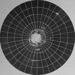
Figure 40.--Range circles and azimuth lines.
D. INFORMATION
The controller obtains most of the information he needs for the control of aircraft directly from the PPI. He keeps track of his own and other combat air patrols on the face of the scope
and knows their location and disposition. The controller can follow movement of strikes, sweeps, and searches and thus be up to date on the current air situation.
E. BLIP INTERPRETATION
When a bogey appears on the scope, the controller has an instantaneous and accurate position on it. By observing the size, shape, and form of the blip he can make an approximate estimate of the number of aircraft in the flight. (Best done on "A" scope.) A few aircraft flying a tight formation may appear the same as a single large aircraft; but if the formation is spread, or if there are a number of planes, the blip will appear thicker than normal or consist of several partially merged blips.
F. TRACKING ON THE SCOPE
Additional information about the target can be obtained by tracking it on the face of the scope. Two types of tracks can be used; the continuous line or the dot method. The former consists of placing the grease pencil or pen at the exact inside center of the blip and drawing back a short line. On each successive sweep of the time base this is repeated on the new blip always being sure to start at the new position of the target and to draw the line back to connect with the last position. If a sharp soft pencil is used, a light, narrow continuous line will result, showing clearly the track of the target.
If the dot method is used, the operation is similar, except that successive positions of the target are not joined, and, as a result, the track appears as a line of dots. This method does not show course changes of the target quite so accurately as the continuous line method, but it does have the distinct advantage of revealing radical changes in the target's speed.
If information about the target's speed is desired, the dot method is used; otherwise, the continuous line is preferable.
The dot method is also more useful for dead reckoning the movement of targets on the PPI.
G. WIND
Another factor to be considered in interpreting the track on the scope is wind aloft. In the
--46--
case of the stationary base, the track on the scope representing the track of the target over the ground is also the heading of the target under no-wind conditions. It there is wind at the altitude at which the target is flying, his track over the earth may not be the same as his heading. In the case of the shipboard set, the track on the scope is the result not only of the effect of the wind on the target but also the effect of the movement of the ship. Both factors must be considered in determining the target's true heading. This may take the form of a rough estimate by the controller or the information can be obtained more accurately by the use of a computer and the intercept plot.
H. VARIATION
In addition to correcting for wind factors, this true heading must be converted to magnetic heading by applying the variation existing in the locality. All headings and vectors given to pilots must be in terms of magnetic rather than true headings to correspond with the magnetic compass. When operating from a permanent base, this is a simple addition or subtraction of a constant figure, but when operating from shipboard the controller is confronted with the problem of a continual change in the amount of variation as his ship changes localities. Thus when the controller wants a blip on one part of his scope to go to another part of his scope (perhaps a point of intersection with an unidentified blip), he must give the pilot of his friendly % aircraft a heading which makes that blip move across the scope to that point. The heading given will not be the true bearing of the point of destination from the present position of the blip but will be a heading which takes into account relative wind (i.e., ship's motion and the winds aloft) and magnetic variation.
I. SPEED OF RELATIVE MOTION WITH RESPECT TO SHIP
Winds aloft and ship's motion are also factors in determining the true air speed of a target The speed of movement of the target's blip
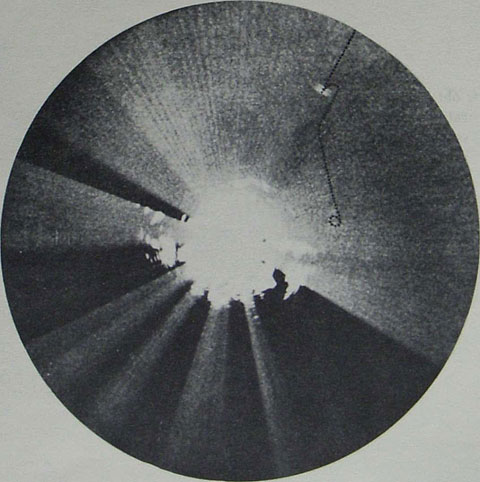
Figure 41 a.--Tracking on the PPI scope.
--47--
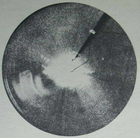
Figure 41 b.---Tracking on the PPI scope.
across the scope is speed of relative motion with respect to the ship.
This figure can be fairly accurately obtained by plotting the movement against accurate times and converting to nautical miles per hour. The resulting figure must be adjusted to allow for the effect of ship's motion and the winds aloft. To illustrate: if a ship is on a heading of 180* at 20 knots and there is a 10-knot wind aloft from 360°, it is evident that the speed of relative motion (speed of the blip across the scope) of a plane heading south indicating 200 knots will be less than the speed of relative motion of a plane heading north at the same indicated speed. By using the dot method of tracking, the controller can make rough estimates of the relative speed of two aircraft, or two groups of aircraft but he must consider the relative wind (i.e., ship's motion and wind at altitude) in determining whether there is a difference in true air speed.
If more accurate information is desired, it can be obtained for the controller by the use of a plot table and computer.
J. RANGE OF COVERAGE
The size of the PPI scope and the range of coverage used have considerable bearing on the amount of information which can be obtained from the scope. A 12-inch scope will give a much clearer picture than a 5-inch or 7-inch scope. The blips are larger and their movement is more pronounced and noticeable. Consequently, a change in heading by a target can be picked up on the larger scope more quickly than on a smaller one.
Further, utilizing the same range scale on a 5-inch scope as on a 12-inch scope, it will be apparent that range resolution is considerably finer on the larger scope. Thus two target echoes will merge and their relative positions will become indistinguishable when further apart on the smaller scope than on the larger scope. It may be possible to follow the friendly
--48--
plane to within a mile of the target without loss of control on a large scope whereas on a smaller scope this minimum distance may be as much as 3 or 4 miles. The question of what range to use on the scope is decided by the controller in view of the tactical situation. If interception of the enemy is desired at maximum range, a long-range scale will be used on the scope. This will result in less accurate target information but greater range of pick-up.
If accurate close control is desired, a shorter range will be used, but one which will still give an initial pick-up at sufficient range to make an interception before the enemy has closed too near.
K. FADES
Certain defects in the PPI picture are attributed to the fault of radar rather than the type of presentation. Fading is present in all air search radars of the SK type. At certain ranges and at certain altitudes the target blip fades from the scope because the plane passes through a null area in the lobe pattern of the radar. These fades may be of short duration or may extend for several miles.
In centimeter-wave sets, where the concentrated cone of energy is beamed at the target, there theoretically should be no fading; and normally, at angles of elevation above 4° there is no fading in the true sense of the word. Below 4° there is some reflection of energy from the earth and narrow fade zones may appear. It is also possible that lack of information on the scope may be due to the inability of the operator to keep the beam on the target. At extreme ranges the return may fluctuate in strength to such an extent that it fades in and out on the scope.
More modern radars, designed toward the end of the war, and still in service use, have eliminated much of the fading problem. However, this was done at the expense of range.
But controllers can work through fading. If the controller accurately tracks a target blip on his PPI scope and the blip fades, he can continue the track in the same direction and advance it at the same rate and thus secure a series of fairly accurate dead reckoned position. The greater the controller's skill at tracking, the more accurate this dead reckoning will be.
L. IFF SIGNALS IN TRACKING
Another aid to the tracking is the IFF signal on friendly aircraft which may continue to appear even through the blip has faded. This signal, more accurate in range than in bearing, gives the controller useful information. Therefore, by simply continuing the direction of the friendly track to the range indicated by the IFF signal, an even more accurate position is possible.
M. LOW-FLYING AIRCRAFT
A further weakness in the PPI picture, again the fault of radar itself, is its inability to detect low-flying aircraft. In this respect the centimeter sets are superior in performance to the SK, SC-2 sets. If the controller has available only the latter type set, he must keep the friendly aircraft under his control at an altitude high enough to insure a return on his scope. In some instances the IFF signals can be used to approximate the position of a plane too low to produce a return on the scope.
N. JAMMING
A defect inherent in radar itself is its susceptibility to jamming. This is explained in greater detail in chapter VII of RADONE A.
O. CORRELATION OF PLOTTING AND THE PPI
The controller of aircraft needs a continuous graphic presentation of the total air situation to enable him properly to evaluate all known information and thus decide how best to control his available aircraft. This presentation can either be on a plotting board or, if the screen is not excessively cluttered, on a PPI tube, with increasing use being made of the PPI as the medium through which to control.
In using the plotting board, information received from the various radars is plotted in appropriate symbols, and continuous tracks are kept of both friendly and enemy planes.
Radar Bulletin No. 4 (RADFOUR), "The Air Plotting Manual" covers completely the
--49--
mechanics of air plotting; and its relation to control of aircraft is self-evident to the reader of that publication. Therefore for the purposes of the present manual, the principles and techniques of plotting will not be repeated.
Though the PPI whenever available is being used by the controller to control aircraft, the plotting board still has a definite place in the the control picture. It may assume a secondary role but its importance cannot be minimized in presenting a graphic, current display of air events.
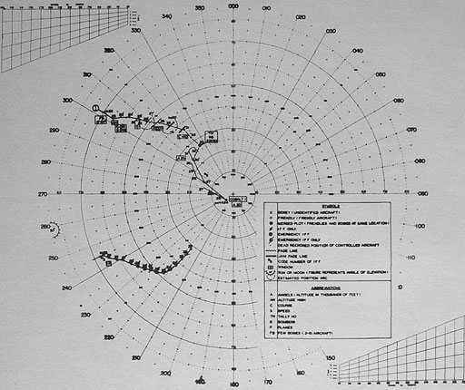
Figure 42--The air-plot.
A great deal of information not readly available from the PPI is immediately evident on a properly maintained plot. Due to the physical size of the PPI, its presentation is seen only by the
controller, whereas the plotting board is visually accessible to everyone in the CIC. Figure 1 shows how course, speed, altitude, and other pertinent information are recorded in plain sight for ready reference. Furthermore, speeds and courses can be determined more accurately on a large plotting board than on a 12-inch PPI scope.
From an interception standpoint the maintenance of a plot is very necessary even though the actual interception is being controlled from the PPI. The much larger presentation on the plot gives a clearer picture of the relative movement of a raid and intercepting fighters.
The plot also serves as a summary of information from a number of sources, whereas the
--50--
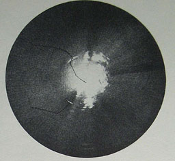
Figure 43.--Human error anal time log it eliminated on PPI plot.
PPI is necessarily restricted to one radar source at a time. Power failure, mechanical defects, jamming, and other radar countermeasures may ruin the PPI picture whereas the plot presents a continuous picture by dead reckoning or from information received from other sources aboard ship or from other ships.
The chief advantage of the PPI over the plot for conducting interceptions is a current, electronic picture which eliminates time lag and the possibility of human error, but the plotting board still has a vital back-stop function in the control of aircraft.
A relative plot showing the location of search planes is maintained at all times in hunter-killer work. Though the DRT gives the best overall picture of the situation, most controllers prefer the plotting board with the PPI for actual control. Its use is covered more fully in the chapter on Hunter-Killer operations (chapter 17).
--51--
Table of Contents
Previous Chapter (5)
Next Chapter (7)


