
|
| OP 1719 |
GUN FIRE CONTROL SYSTEM
MARK 37
OPERATING INSTRUCTIONS

|
21 APRIL 1949 |
NAVY DEPARTMENT
BUREAU OF ORDNANCE
WASHINGTON 25, D. C.
| 21 April 1945 |
| ORDNANCE PAMPHLET 1919 |
| GUN FIRE CONTROL SYSTEM MARK 37 — |
|
OPERATING
INSTRUCTIONS |
| OP 1060 | Gun Director Mark 37 | |
| OP 1063 | Stable Element Mark 6 | |
| OP 1064 | Computer Mark 1 | |
| OP 1076 | Radar Equipment Mark 12 | |
| OP 1153 | Radar Equipment Mark 22 | |
| OP 1651 | Radar Equipment Mark 25 | |
| OP 1772 | Radar Equipment Mark 12 (formerly Ships 270A) | |
| OP 1775 | Radar Equipment Mark 22 (formerly NavShips 900,850) | |
| OP 1788 | Radar Equipment Mark 25 (formerly NavShips 900,975 | |
| 4.
This publication is |
| A. G. Nobel, | |
| Rear Admiral, U.S. Navy | |
| Chief of the Bureau of Ordnance | |
| Acting |
CONTENTS
| Page | Page | |||
| Chapter 1—INTRODUCTION | 1 | Chapter 3—AIR TARGETS | 23 | |
| Purpose | 1 | Introduction | 23 | |
| Scope | 1 | 3.1 Visible Air Targets (with Radar | ||
| Equipment Mk 12) | 23 | |||
| Chapter 2—STAND-BY CONDITION | 3 | Target Acquisition | 23 | |
| Introduction | 3 | Gun Director | 23 | |
| Communication | 3 | Tracking | 24 | |
| 2.1 The I.C. Room | 6 | Gun Director | 24 | |
| 1.C. Switchboard | 6 | Plotting Room | 26 | |
| 2.2 The Radar Room | 6 | Gun Mount | 26 | |
| Radar Equipments Mk 12 and | Firing | 26 | ||
| Mk 22 | 6 | Gun Director | 27 | |
| Radar Equipments Mk 25 | 6 | Evaluation Method | 27 | |
| 2.3 The Plotting Room | 7 | Time Constant | 27 | |
| Fire Control Switchboard | 7 | 3.2 Obscured Air Targets (with Radar | ||
| Fuze Panel | 8 | Equipments Mk 12 and Mk 22) | 28 | |
| Director Panel | 8 | Target Acquisition | 29 | |
| Computer Panel | 8 | Gun Director | 29 | |
| Stable Element Panel | 8 | Tracking | 30 | |
| Gun Mount Panel | 8 | Gun Director | 30 | |
| Stable Element Control Panel | 8 | Plotting Room | 30 | |
| Stable Element | 9 | Gun Mount | 31 | |
| Selector Drive | 9 | Firing | 31 | |
| Computer | 9 | Evaluation Method | 31 | |
| Control Unit | 10 | 3.3 Operation with Radar Mk 25 | 31 | |
| Computer Unit | 10 | Target Acquisition | 31 | |
| Indictor Unit | 11 | Tracking | 34 | |
| 2.4 The Gun Director | 11 | One-Man Control | 34 | |
| Gun Director Pedestal | 11 | Target Acquisition | 34 | |
| Radar Operator's Station | 12 | Tracking | 34 | |
| Radar Equipments Mk 12 and | Evaluation Method | 35 | ||
| Mk 22 | 12 | 3.4 Alternate Methods | 35 | |
| Radar Equipment Mk 25 | 14 | Optical Ranging | 36 | |
| Pointer's Station | 15 | Salvo Firing | 35 | |
| Trainer's Station | 16 | Local Control | 35 | |
| Assistant Control Officers Station | 17 | Manual Tracking with Radar | ||
| Range Finder Operator's Station | 18 | Equipment Mk 25 | 36 | |
| Control Officer's Station | 18 | Chapter 4—SURFACE TARGETS | 37 | |
| 2.4 The Gun Mount | 20 | Visible Surface Targets | 37 | |
| Controller Line Switches | 20 | Method 1 | 37 | |
|
Gun Captain's Station | 20 | Method 2 | 38 | |
| Gun Train Drive | 20 | Obscured Surface Targets | 39 | |
|
Gun Elevation Drive | 20 | |||
|
Fuze Setter | 20 | |||
|
2.6 Summary | 21 |
-iii-
| Page | Page | |||
| Surface Spotting (with Radar | Chapter 5—SHORE BOMBARDMENT | 47 | ||
| Equipment Mk 25) | 39 | Direct Fire | 47 | |
| Estimating Spots | 41 | Indirect Fire | 47 | |
| Time Constraints for Surface Fire | 42 | Tracking | 47 | |
| Manual rate Control | 42 | Firing | 47 | |
| Illumination | 43 | Offset Fire | 47 | |
| Star Shells | 43 | Method 1 | 47 | |
| Search Lights | 44 | Method 2 | 48 | |
| Alternate Methods | 44 | A Sample Problem | 49 | |
| Selected Firing | 44 |
Illustrations
| Figures | Page | Figures | Page | |
| Frontispiece— | 17. Assistant Control Officer's Station— | |||
| Gun Fire Control Station Mk 37 and | Gun Director Mk 37 | 18 | ||
|
Associated Stations | vi | 18. Rangefinder Operator's Station— | ||
| 1. Typical Communications Set-up—Gun |
Director Mk 37 | 19 | ||
|
Fire Control System Mk 37 | 4 | 19. Control Officer' s Station—Gun | ||
|
2. Primary Control Circuits on a Two- | for Mk 37 (Equipped with Radar | |||
|
System Ship | 5 |
Equipment Mark 12) | 19 | |
|
3. Radar Control Consol Mk 5 | 7 | 20. Control Officer' s Station—Gun | ||
| 4. Controller (Antenna Motor) | 7 |
for Mk 37 (Equipped with Radar | ||
|
5. Radar Tracker (Automatic) | 7 | Equipment Mk 25) | ||
|
6. Control Unit (Power) | 7 | for Mk 37 (Equipped with Radar | 20 | |
|
7. Stable Element Control Panel | 9 |
21. Operation of Gun Fire Control | ||
|
8. Stable Element Mk 6 | 9 | System Mk 37 (Equipped with | ||
|
9. Selector Drive Mk 1 | 9 | Radar Equipment Mk 12) Against | ||
|
10. Control Unit Operating Controls— | 9 | Visible Targets | 22 | |
|
Computer Mk 1 | 10 |
22. Control Officer's Station—Gun Direc- | ||
|
11. Computer and Indicator Unit Operat- | tor Mk 37 (Equipped with Radar | |||
|
ing Controls—Computer Mk 1 | 11 | Equipment Mk 12) | 22 | |
|
12. Radar Operator's Station—Gun Direc- | 23. Radar Operator's Station—Gun Direc- | |||
|
for Mk 37 (Equipped with Radar |
tor Mk 37 (Equipped with Radar | |||
|
Equipments for Mk 12 and Mk 22 | 12 | Equipments for Mk 12 and Mk 22 | 24 | |
|
13. Radar Operator's Station—Gun Direc- | 24. Rangefinder Operators Station—Gun | |||
|
tor Mk 37 (Equipped with Radar | Director Mk 37 | 25 | ||
|
Equipment Mk 25) | 14 | 25. Pointer's Station—Gun Director | ||
|
14. Pointer's Station—Gun Director- | Mk 37 (Equipped with Radar | |||
|
Mk 37 (Equipped with Radar |
Equipments Mk 12 and Mark 22) | 25 | ||
|
Equipments Mk 12 and Mark 22) | 15 | 26. Trainer's Station—Gun Director | ||
|
15, Trainer's Station—Gun Director | Mk 37 (Equipped with Radar | |||
|
tor Mk 37 (Equipped with Radar | Equipment Mk 12) | 25 | ||
|
Equipment Mk 12 ) | 16 | 27. Operating Controls—Computer Mk 1 | 26 | |
|
16. Trainer's Station—Gun Director | 28. Additional Operating Controls—Com | |||
|
tor Mk 37 (Equipped with Radar | puter Mk 1A (After Ordalt 2331A) | 27 | ||
|
Equipment Mk 12 ) | 17 |
-iv-
| Figures | Page | Figures | Page | |
| .29. Time Constants for Air Targets— | 37. Operation of Gun Fire Control System | |||
| (Before and after Ordalt 2331A) | 28 | Mk 37 Against Visible Surface | ||
|
30. Effect of Sensitivity Push Button on | Targets. Method 2. | 39 | ||
| Time Constants | 28 |
38. Radar Console Mk 5 | 40 | |
|
31. Operation of Gun Fire Control System | 39. Typical Splash Indications | 40 | ||
|
Mk 37 Against Obscured Air Targets | 29 | 40. Splash Indications of a Six Gun Salvo | 41 | |
|
32. Operation of Gun Fire Control System |
41. Time Constants for Surface Targets | 42 | ||
|
Mk 37 (Equipped with Radar | 42. Manual Rate Control—Computer Mk 1 | 43 | ||
| Equipments Mk 25) Against Visible |
43. Assistant Control Officer's Station— | |||
|
Air Targets | 32 | Gun Director Mk 37 | 44 | |
|
33. Pointer's and Trainer's Station—Gun | 44. Stable Element Mk 6 | 45 | ||
|
Director Mk 37 (Equipped with |
45. Operation of Gun Fire Control System | |||
|
Radar Equipment Mk 25) | 33 | Mk 37—Offset Fire—Method 1 | ||
|
34. Radar Console Mk 5 | 33 | (Point "Oboe" Method) | 46 | |
|
35. Operation of Gun Fire Control System | 47. Operation of Gun Fire Control System | |||
|
Mk 37 Against Visible Surface |
Mk 37—Offset Fire—Method 2 | |||
|
Targets. Method 1. | 37 | (Offset Method) | 48 | |
|
36. Operating Controls for Surface Fire— | 48. A Shore Bombardment Problem | 48 | ||
|
Computer Mk 1 | 38 | 49. Type B Radar Presentations of the | ||
|
|
Problem in Figure 48 | 49 | ||
|
Equipment Mk 12 ) | 17 |
-v-
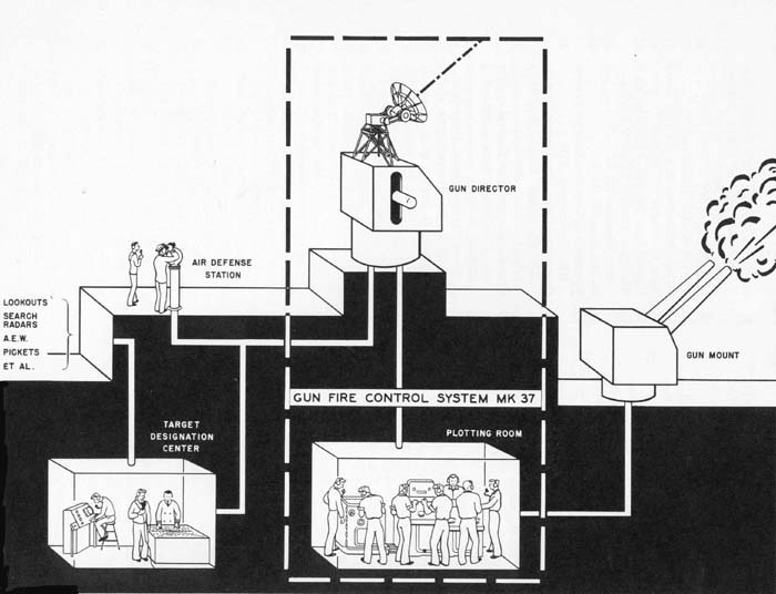
Frontispiece. Gun Fire Control System Mk 37 and Associated Stations
-vi-
CHAPTER 1
INTRODUCTION
|
Purpose
The nature of the Gun Fire Control System Mk 37 suggests the following division of the presentation of operating instructions:
In this pamphlet a chapter is devoted to each of these divisions. The chapters containing instructions for operation against air targets and surface targets are further subdivided according to the tactical situation; each giving the preferred methods of engaging visible targets (i.e., surprise attacks, daytime surface engagements, etc.) and obscured targets (i.e., night attacks, long range engagements, etc.). In certain methods are not for different tactical situations but are secondary methods of utilizing the equipment to cope with the same tactical problem. Where more than one method of operation for any tactical situation is given, the first method described is recommended if the operating conditions and the material condition of the equipments permit such a procedure. It is recognized, however, that in the use of certain ordnance equipment which requires human supervision, control, or operation, there are factors associated with the personalities of the available humans which, for a particular ship, may make most effective a procedure considered of secondary merit by other organizations. The chapter on shore bombardment describes methods that may be employed for each of the following situations:
Scope |
-1-
|
This description is generally applicable to all Gun Fire Control Systems Mk 37. It is specifically applicable to a system including the following components:
|
-2-
CHAPTER 2
STANDBY CONDITION
|
Introduction Communications Scheme 1. Figure 1 is a block diagram of a typical communications setup for a Gun Fire Control System Mk 37 in control of a portion of the ship's antiaircraft battery. Considerable fleet experience indicates that this setup is satisfactory. Its principal features are as follows. As shown
by the figure, the air defense officer is given direct communication with the
director control officer, the plotting room officer, and the evaluator via the
air defense circuit (5JP). The control officers of other antiaircraft systems
on the same ship may also be on this 5JP circuit. Since the air defense officer
may receive target status information, target designations, etc. on this circuit
from the evaluator at the target designation center; this information reaches
the director control officer and the plotting room officer at the same time, thereby
allowing more time to take appropriate action than if this information were to
be relayed through several channels. The director pointer is placed on the 5JP
circuit to maintain contact between the air defense officer and the director crew
whenever the director control officer has switched to his gun control circuit
(UP), or is standing at the slewing sight. The switchboard operator, in plot,
is placed on the 5JP circuit in order that he may take direct action on orders
involving switching operations such as changes in battery setups. The gun control
circuit (UP) is used primarily to establish communications between the director
control officer, the computer officer, and the mount captains. This circuit serves
as the only means of communication from the mount captains to the director control
officer as the battle announcing circuit (17MC) is not reversible. The assistant
control officer on the UP circuit in the director normally acts directly for the
director control officer in matters appropriate to the UP circuit when the latter
is on the air defense circuit (5JP). The computer operator (elevation), mount
and director trainers, and mount pointers are on the UP circuit for information
only (such as early receipt of |
-3-
Figure I. Typical Communications Setup—Gun Fire Control System Mk 37.
"action" commands) and ordinarily make no use of the speaking section of their phones. When illumination is required, the assistant control officer shifts to the illumination control circuit (1JNT) and controls illumination, communicating either with the searchlight captains, or with the mount captains of star shell mounts and with the star shell computer operator. Under this arrangement, the director trainer is the director UP talker. The fuze setter's (JK) and sight setter's (JQ) circuit outlets are so located that they may be used as emergency transmission units for the computer outputs. In addition, good procedure dictates a continuous word transmission of the appropriate values on these circuits even though the primary (synchro) transmission is believed to be effective. The rangefmder's circuit (JW), aside
-4-
from being an auxiliary range transmission circuit, allows the rangefinder operator to give estimates of target angle to the computer operator (bearing). The radar information circuit (JS) is used for transmitting designation or identification data; this may or may not be found to be active. In any case, both the radar operator and rangefinder operator should receive the earliest target designations.
Scheme 2. Scheme 2 is illustrated in figure 2. The principal basic variation in this scheme from scheme 1 requires changes in the organization at the air defense stations and in the target designation center. Sector designating officers in the target designation center and sector air defense officers in the topside air defense station (s) replace the indicated single gunnery liaison officer and single air defense officer. By providing key personnel with selector switches, this system provides an efficient method for giving each sector a sufficient number of channels for communication with the control and designation centers.
Figure 2. Primary Control Circuits on a Two-System Ship.
-5-
|
2.1 THE IC ROOM IC Switchboard
2.2 THE RADAR ROOM At the present time, most Gun Fire Control Systems Mk 37 are equipped with either Radar Equipments Mk 12 and Mk 22 or Radar Equipment Mk 25. The below-decks operations required to place these equipments in the standby condition are as follows: Radar Equipments Mk 12 and Mk 22 Radar Equipment Mk 25 |
-6-
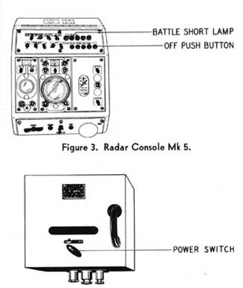 | 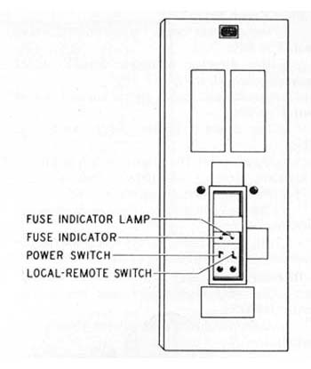 | |||
| Figure 4. Controller (Antenna Motor). | Figure 5. Radar Tracker (Automatic) | |||
|
| 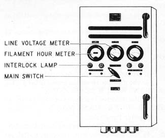
Figure 6. Control Unit (Power) | |||
| ||||
| Fire
Control Switchboard Since several different types and modifications of fire control switchboards are furnished with Gun Fire Control Systems Mk 37, these operating instructions are necessarily general. The location of certain switches varies from board to board, hence no attempt will be made to show the location of the switches. Instead, they will be designated by their functions. In any particular installation, specific switches thus referred to should be easily identifiable by their label plates. | ||||
-7-
| Fuse
Panel. Set: a. the director cease firing contact maker switch at ON; b. the director pointer's firing contact maker switch at ON; c. the director salvo signal contact maker switch at ON; d. the director heater supply switch at ON; e. the director DC supply switch at ON; f. the director AC supply switch at ON; g. the computer AC supply switch at ON; h. the searchlight shutter control motor switch at ON; i. the gun mount firing and battle announcing rotary switch at 17MC and 2PA. Director Panel. Set: a. the star shell range spot transmitter switch at ON; b. the star shell elevation spot transmitter switch at ON; c. the star shell deflection spot transmitter switch at ON; d. the own ship course receiver switch at ON; e. the range spot transmitter switch at ON; f. the elevation spot transmitter switch at ON; g. the deflection spot transmitter switch at ON; h. the range spot receiver switch at ON; i. the range transmitter switch at ON; j. the director elevation transmitter switch at TRANS NO. 1 & TRANS. NO. 2; k. the director train transmitter switch at TRANS. NO. 1 & TRANS. NO. 2. Computer Panel. Set: a. the range spot receiver switch at ON; b. the elevation spot receiver switch at ON; c. the deflection spot receiver switch at ON; d. the director train receiver switch at the proper director; e. the director elevation receiver switch at the proper director; f. the director train control (auto) transmitter switch at ON; g. the director elevation control (auto) transmitter switch at ON; h. the sight angle and sight deflection transmitter switch at ON; i. the fuze transmitter switch at ON; j. the own ship course and own ship speed switch at O.S.C. & O.S.S.; k. the star shell fuze order transmitter switch at ON; l. the director elevation control (ind.) transmitter switch at ON; m. the director train control (ind.) transmitter switch at ON; n. the train parallax transmitter switch at ON; o. the elevation parallax transmitter switch (if any) at ON; p. the gun train order transmitter switch at NO. 1 IND. & NO. 2 AUTO, or NO. 1 AUTO. & NO. 2 IND.; q. the gun elevation order transmitter switch at NO. 1 IND. & NO. 2 AUTO, or NO. 1 AUTO. & NO. 2 IND. Stable Element Panel. Set: a. the cross-level transmitter switch at ON; b. the own ship course and own ship speed receiver switch at O.S.C. & O.S.S. G Gun Mount Panel. Set: a. the fuze receiver switch at FUZE SETTING; b. the gun train (auto.) switch at G.T.O.; c. the gun elevation (auto.) switch at G.E.O.; d. the gun train (ind.) switch at G.T.O. & PARALLAX; e. the gun elevation (ind.) switch at G.E.O.; f. the sight setter's indicator switch at ON. Stable Element Control Panel |
-8-
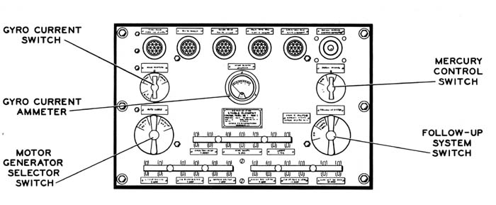 | |||
| Figure 7. Stable Element Control Panel. | |||
|
d.
Determine when the gyro is up to speed by means of the gyro current switch and
the gyro current ammeter. (When the gyro is up to speed, the ammeter should read
approximately J..1 amps, for each phase.) Stable Element Selector Drive Computer | 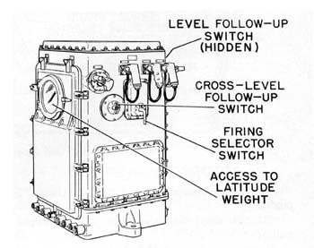 Figure 8. Stable Element Mk 6. | ||
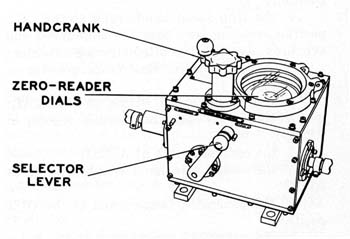 Figure 9. Selector Drive Mk I. | |||
-9-
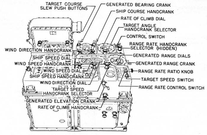 | ||
| Figure
10. Control Unit Operating Controls—Computer Mk I. |
|
Control
Unit (fig. 10). Set: Computer Unit (fig. 11). Set: |
-10-
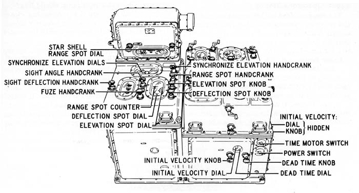
Figure 11. Computer and Indicator Unit Operating Controls—Computer Mk I.
|
of
dead time for the gun mounts to be controlled ; |
| 2.4 THE GUN DIRECTOR |
|
Since there are several stations in the
gun director, the operating instructions are subdivided into the operations that
should be performed at each of the following locations: Gun Director Pedestal |
-11-
|
Radar
Operator's Station Radar
Equipments Mk 12 and Mk 22 (fig. 12). |
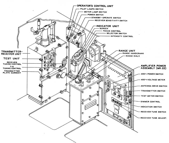
Figure
12 Radar Operator's Station—Gun Director Mk 37 (Equipped with Radar Equipments
Mk
12 and Mk 22).
-12-
|
defined
sweep. (In order to preserve night vision, the intensity should be kept as low
as possible for good operation.) RADAR EQUIPMENT MK 22. *If a target is not available, the tuning adjustment may be made by using the test unit of Radar Equipment Mk 12. |
-13-
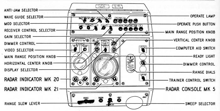
Figure
13. Radar Operator's Station—Gun Director Mk 37 (Equipped with Radar Equipment
Mk 25).
|
reference.
This setting should be maintained when automatic frequency control is used because
of the interaction between the two circuits. Radar Equipment Mk 25. |
-14-
|
MAIN RANGE POSITION knob so
that the start of the sweep is one-fourth inch from the left edge of the indicator
screen. Pointer's
Station (fig. 14) |
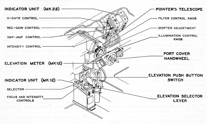
Figure 14. Pointer's Station—Gun Director Mk 37 (Equipped with Radar Equipments Mk 12 and Mk 22)
-15-
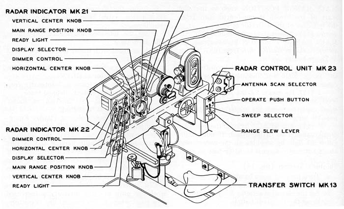
Figure 15. Pointer's and Trainer's Station—Gun Director Mk 37 (Equipped with Radar Equipment Mk 25).
|
g'.
If equipped with Radar Equipment Mk 25 (fig. 15) : Trainer's
Station (fig. 16) |
-16-

Figure 16. Trainer's Station—Gun Director Mk 37 (Equipped with Radar Equipment Mk 12).
|
(1)
Set the indicator unit (Radar Equipment Mk 12) selector at TRAIN. Assistant
Control Officer's Station (fig. 17) |
-17-
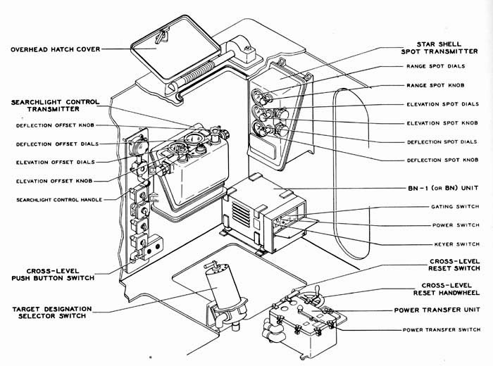
Figure
17. Assistant Control Officer's Station—Gun Director Mk 37.
|
o.
At the BN-1 (or BN) unit, set the gating switch at OFF; the keyer switch at ON;
and the power switch at ON. Rangefinder
Operator's Station (fig. 18) Control
Officer's Station (fig. 19) |
-18-
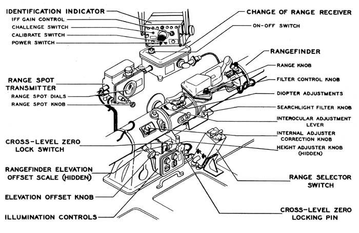
Figure
18. Rangefinder Operator's Station—Gun Director Mk 37.
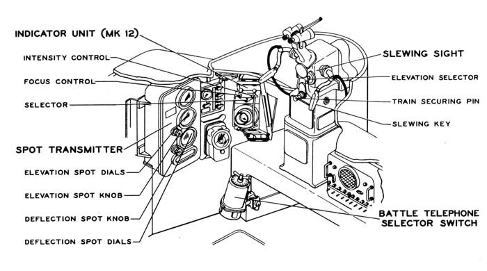
Figure
19. Control Officer's Station—Gun Director Mk 37 (Equipped with Radar Equipment
Mk 12).
-19-
|
b.
Press the slewing key. |
|
Figure
20. Control Officer's Station—Gun Director |
| 2.5 THE GUN MOUNT |
|
Gun
Fire Control Systems Mk 37 are used to control a variety of guns, mounts, and
turrets. The following description of operations that must be performed at the
gun mount (or turret) is necessarily general. Specific instructions for performing
the operations outlined below can be found in the OP applying to the type of gun
mount (or turret) in question. The applicable OP's are as follows: Controller Line Switches Gun Captain's Station Gun Elevation Drive Fuze Setter |
-20-
| 2.6
SUMMARY |
|
The operations outlined in sections 2.1 to 2.5 place the Gun Fire Control System Mk 37 in the stand-by condition. This section briefly summarizes the status of the gun director and the plotting room equipments when in the stand-by condition. Gun director. The gun director is completely energized. Cross level and the parallax corrections are being received automatically. The computer aid circuits are so connected that the generated quantities will be received from the computer at the train and elevation drives, the range finder, and the radar range unit. The radar equipment is energized and radiating so that it may be utilized as search equipment during the stand-by period. Only a few switching operations are required in shifting to the tracking phase; no waiting period is necessary. The gun director complement consists of six men when fully manned. When equipped with Radar Equipment Mk 25 Mod 2, the gun director may be placed in the stand-by condition with only one operator, the director trainer. Plotting room. The stable element is energized and in automatic control, continuously transmitting level and cross level to the computer, cross level to the gun director, and level to the searchlights (in certain installations only). Except for the time motor, the computer is completely energized and in automatic control. The sensitivity of Computers Mk 1A is at its maximum value. To commence tracking it is only necessary to introduce estimated values of target speed and target course (or target angle), and energize the time motor. In addition to transmitting parallax, fuze setting, and gun orders, the computer is set up for transmitting generated quantities to the gun director to aid in the tracking problem. |
-21-
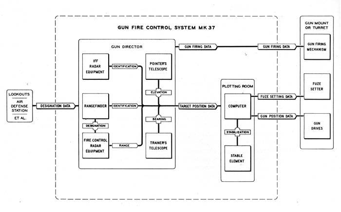
Figure 21. Operation of Gun Fire Control System Mk 37 (Equipped with Radar Equipment Mk 12) Against Visible Air Targets.
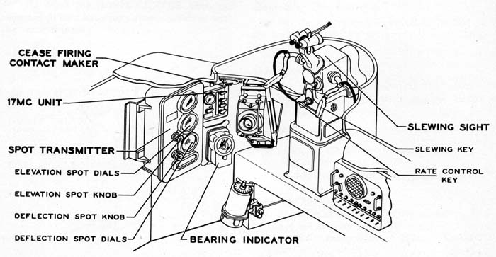
Figure 22. Control Officer's Station—Gun Director Mk 37 (Equipped with Radar Equipment Mk 12).
-22-
AIR TARGETS
|
Introduction The problem of engaging a target can be divided into three phases: (1) target acquisition, (2) tracking, and (3) firing. The first phase, target acquisition, commences when a target is designated to the director. It ends when the target is centered in the director scopes and the director control officer informs plot that the gun director is "ON TARGET." The second phase, tracking, is the time that the director stays "ON TARGET." The fire control problem is solved during this phase. The third phase, firing, is started by the "COMMENCE FIRING" order and ended by the "CEASE FIRING" order. Operations of the tracking phase are continued during this phase. 3.1 VISIBLE AIR TARGETS (WITH RADAR EQUIPMENT MK 12) This section outlines the method of engaging visible air targets for systems equipped with Radar Equipment Mk 12. The procedure for systems equipped with Radar Equipment Mk 25 is given in section 3.3. Since most air targets that are visible at the time of initiating action against them are undesirably close, the quickest and most direct method of engaging them must be employed. Figure 21 indicates the over-all function of the major units of the Gun Fire Control System Mk 37 when it is equipped with Radar Equipment Mk 12 and employed against a visible air target. The most effective method of operating a system so equipped, utilizes optical tracking in train and elevation, and radar tracking in range. The optical range finder is used for designation and identification purposes, serving to designate the proper target pip to the radar operator by giving him an approximate range, and helping in the identification problem by visual recognition when the IFF response is not conclusive. As indicated by figure 21, the stable element furnishes stabilization data to the computer. From the target position data, received from the gun director, and the stabilization data, the computer determines the required fuze setting and gun position data. Firing of the guns is controlled from the gun director. A detailed outline of the target acquisition, tracking, and firing operations follows. Target
Acquisition Gun director. The following operations should be performed at the gun director during the acquisition of a visible target: AT
THE CONTROL OFFICER'S STATION (fig. 22) : |
-23-
|
required for the control officer to be able to put the director sights on the target in a minimum time.) c. Keep
the target centered as well as possible in the slewing sight, give the word "ON
TARGET" to plot, and close the slewing sight rate control key. When the rate control
key is closed, circuits are completed which drive the computer towards the correct
solution. (NOTE: Ordalt 2840 provides the slewing sight rate control key.) |
|
Figure
23. Radar Operator's Station—Gun Director |
| AT THE RADAR OPERATOR'S
STATION (fig. 23) : a. Turn the range hand crank until the target pip at the range designated by the range finder operator is in the notch of the indicator unit screen. This positions the range transmitters at the correct range, which is transmitted to the plotting room. b. Set the auto and computer aid switches at ON. The auto switch automatically keeps the target pip gated, while the computer aid switch energizes the radar change of range receiver and permits increments of range from the computer to assist in keeping the target pip gated. c. Hold the rate-control switch at ON whenever the target pip is in the notch. This completes circuits which permit the radar equipment to correct the computer's solution if it is in error. AT THE ASSISTANT CONTROL OFFICER'S STATION : a. Set the identification indicator (fig. 24) challenge switch at ON. b. Observe the screen of the identification indicator, and inform the control officer whether the target being tracked is a "friendly" or a "bogey." AT THE RANGE FINDER OPERATOR'S STATION (fig. 24) : a. Assist with the recognition problem by viewing the target through the range finder. b. Check range to see that the radar operator has the correct pip in the notch. |
|
Figure
24. Rangefinder Operator's Station—Gun Director Mk 37. |
|
Tracking Gun Director. |
-24-
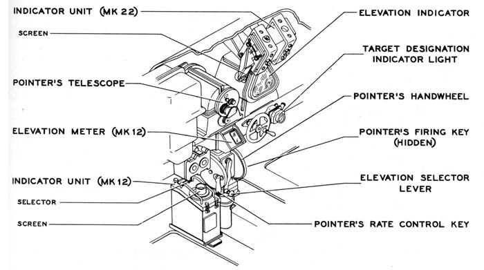
Figure
25. Pointer's Station—Gun Director Mk 37 (Equipped with Radar Equipments
Mk 12 and Mk 22).
|
AT
THE POINTER'S STATION (fig. 25) : |
|
Figure
26. Trainer's Station — Gun Director Mk 37 (Equipped with Radar Equipment
Mk 12). |
-25-
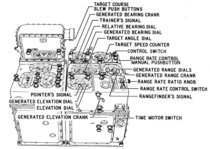
Figure
27. Operating Controls—Computer Mk I.
|
AT
THE RANGE FINDER OPERATOR'S STATION (fig. 24) : Plotting Room. Gun Mount. |
-26-
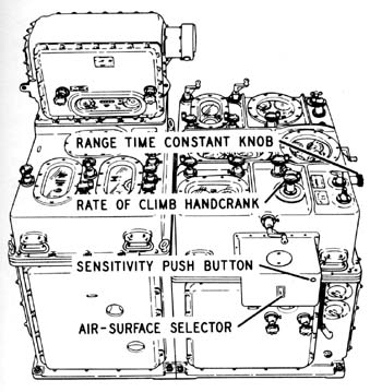
Figure
28. Additional Operating Controls—Computer Mk IA (After Ordalt 2331 A).
|
should
be performed in addition to those outlined for tracking. Gun Director. AT THE POINTER'S
STATION (fig. 25): |
| Evaluation of Method |
|
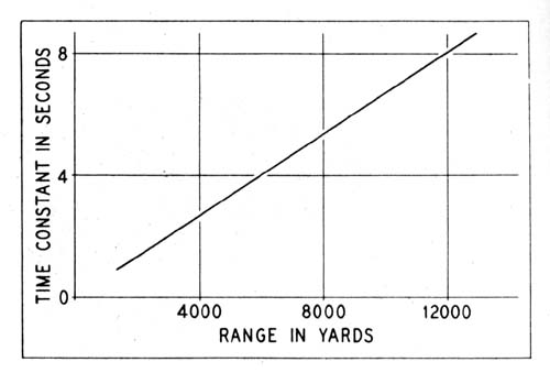
Any method which requires tracking and rate controlling with the slewing sight will not give smooth enough target position data for the system to obtain a stable solution. However, tracking for a. period equal to one or two time constants with the slewing sight rate control key depressed will reduce any error in the original target setup by 65 to 85 percent. This is enough to ease considerably the task of the pointer and trainer in getting "ON TARGET," and permits opening fire almost immediately thereafter. Time constant. |
-27-
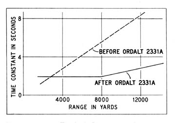 Figure 29. Time Constants for Air Targets—(Before and After Ordalt 2331
A).
 |
|
ties in tracking cause oscillations in the solution and result in an extremely large, undesirable dispersion. These conditions can be improved somewhat if operators remember that before Ordalt 2331A, no matter what the range, a given angular correction at the director (i.e., rotation of pointer's and trainer's handwheels) will cause a given rate correction. Keeping this in mind, the pointer and trainer will find that at long ranges the system is less sensitive because a given change in the target's rate will require less of an angular correction. The pointer and trainer may compensate for this characteristic at long ranges by letting their line of sight go slightly off the target, closing their rate control keys, and bringing it back on. Here again, practice and a "feel" of the system is a major item in obtaining proficiency. After Ordalt 2331A, the best thing for the pointer and trainer to do is to stay ON TARGET and keep their rate control keys closed. After Ordalt 2331A, the computer operator may control the system time constant by means of the sensitivity push button (fig. 28). Time constants for a typical problem are illustrated in figure 30. Assume that a target is approaching with a 500 knot range rate, the two-second change gears are installed in the sensitivity unit, and that the time delay relay is set at three seconds. Starting at point A (fig. 30), the time constant reduces to 2 seconds at 8,000 yards and then remains fixed. Now suppose that the target reaches the point B and maneuvers radically. The computer operator finds that the solution indicators spin (i.e., the time constant is too large to permit quick rate corrections) ; therefore he presses the sensitivity push button. This makes the system time constant decrease as indicated in figure 30. Since instability would result if such a low time constant were maintained over a long period, the previous value of 2 seconds is restored automatically after a lapse of 3 seconds. | |
| 3.2 OBSCURED AIR TARGETS (WITH RADAR EQUIPMENTS MK 12 AND MK 22) | |
|
Figure 31 indicates the functions performed by various units when engaging an obscured air target. It can be seen that the fire control radar equipment furnishes all of the target position data. Since with Radar Equipments Mk 12 and Mk 22 this data is not very smooth, the | |
-28-
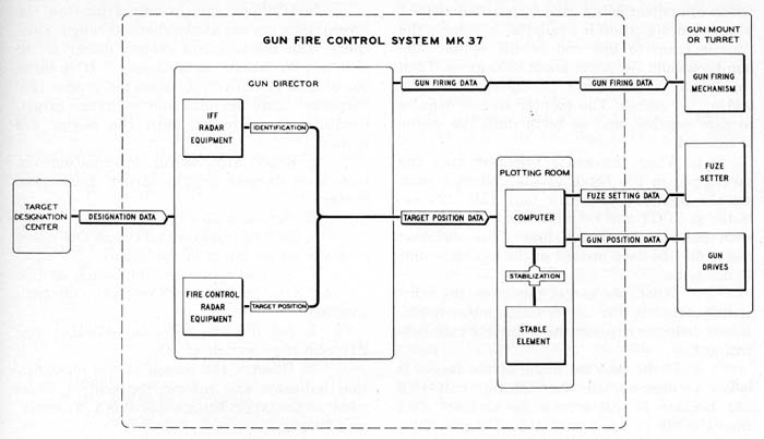
Figure
31. Operation of Gun Fire Control System Mk 37 Against Obscured Air Targets.
|
computer is operated in semiautomatic in order to increase the solution time (reduce the computer sensitivity) so that irregularities in the target position data will not affect the computer solution. In semiautomatic operation, the generated and observed bearing and elevation are matched manually instead of automatically, permitting the computer operators to control the computer sensitivity. Target Acquisition For acquisition of obscured targets, the Gun Fire Control
System Mk 37 must depend principally on information from sources outside the system.
These sources include the ship's search radars, information received via AA coordination
circuits or other channels, A.E.W. etc. The information which these sources provide
is collected, evaluated, and used as the basis for originating target designations
in the target designation center, a central below-decks location. When targets
are located and are to be designated to the Gun Fire Control System Mk 37, the
range and bearing, and in some cases elevation, of these targets is required to
be |
-29-
|
radar
equipment being used. A possible method when no designation is available, is to
have the trainer train to one end of his sector. The pointer should elevate to
about 80 degrees. Then the trainer should train 10 degrees from the end of the
sector. The pointer should depress to zero degrees, and so forth until the sector
is covered. AT THE TRAINER'S STATION (fig. 26) : AT THE RADAR OPERATOR'S STATION (fig. 23) : AT THE ASSISTANT CONTROL OFFICER'S STATION
: AT THE POINTER'S STATION (fig. 25) : AT
THE TRAINER'S STATION (fig. 26) : AT THE RADAR OPERATOR'S STATION (fig. 23) : AT THE COMPUTER (fig. 27) : |
|
c.
Slew target angle to the proper quadrant. The proper quadrant may be determined
by observing the relative bearing and observed range dials. Firing Evaluation of Method 3.3 OPERATION WITH RADAR EQUIPMENT MK 25 Radar
Equipment Mk 25 is an automatic-tracking fire control radar. Since the operation
of certain parts of the gun director is different when this equipment is used,
this section will describe the differences. Operation of equipments not mentioned
in this section is unchanged by the addition of Radar Equipment Mk 25. Except
for the target acquisition phase there is no difference between operation of the
gun director against visible air targets and operation against obscured air targets;
therefore the operating instructions for these types of targets are combined.
With Radar Equipment Mk 25 installed, it is possible to operate the gun director
with one man, the trainer. This type of operation is described later in this section.
Target Acquisition |
-31-
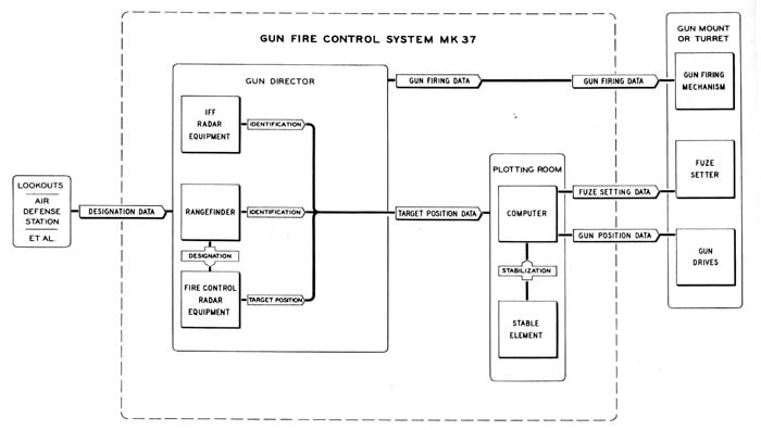
Figure
32. Operation of Gun Fire Control System Mk 37 (Equipped with Radar Equipment
Mk 25)
Against Visible Air Targets
|
of
the Radar Indicator Mk 22. Since this indicator has a long persistence screen,
it is necessary only to pass by the target to have it appear on the screen. (When
the delta E presentation is being used, the display is moved vertically across
the screen by an elevation signal from the computer. This has the effect of stabilizing
the scope presentation and enables the pointer to pass by a target and then determine
its position angle from the scale at the sides of the display.) AT
THE RADAR OPERATOR'S STATION (fig. 34): |
-32-
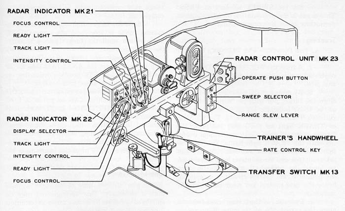
Figure
33. Pointer's and Trainer's Station—Gun Director Mk 37 (Equipped with Radar
Equipment Mk 25).
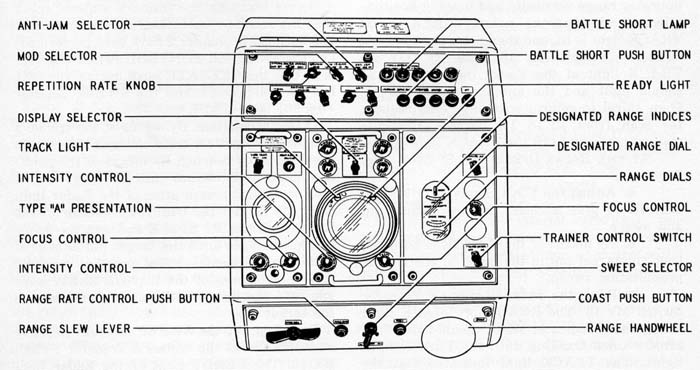
Figure 34. Radar Console Mk 5.
-33-
|
c. Set the SWEEP selector at PRES. This expands the presentation on all indicators permitting more accurate tracking. Tracking One-Man Control The gun director may be operated by one man
if necessary. This arrangement may be employed under such circumstances as condition
2 or condition 3 watches. Target
acquisition. By means of the trainer's handwheel (fig. 33), train the gun
director to the designated bearing. By means of the pointer's handwheels elevate
until the target pip is seen on the AE presentation of the Radar Indicator Mk
22. Set the DISPLAY selector of the Radar Indicator Mk 22 at E and turn the pointer's
handwheels until the target pip is aligned with the horizontal index on the indicator
screen. By means of the RANGE SLEW lever (fig. 33), slew range until the range
mark is on the target pip. |
-34-
|
the RANGE SLEW lever, set the range mark one-sixteenth inch below the target pip on the type B presentation of the Radar Indicator Mk 21. By means of the pointer's and trainer's handwheels, keep the target pips centered on the indicator screens. Continue in this fashion until the TRACK light of the Radar Indicator Mk 21 lights. Evaluation of Method 3.4 ALTERNATE METHODS Some of the following procedures are outlined to assist in the operation of the Gun Fire Control System Mk 37 in the event of a materiel casualty, while others are merely secondary methods of using the equipments. Optical Ranging Salvo
Firing Local Control |
-35-
|
Manual
Tracking with Radar Equipment Mk 25 |
-36-
SURFACE TARGETS
|
Visible
Surface Targets Method 1. Figure 35 shows the function of the elements of the Gun Fire Control System Mk 37 when using this method to engage a visible surface target. The over-all operation of the system is almost identical with that used (fig. 21) to engage visible air targets, the only differences being in the operation of the computer. AT THE COMPUTER (fig. 36) : |
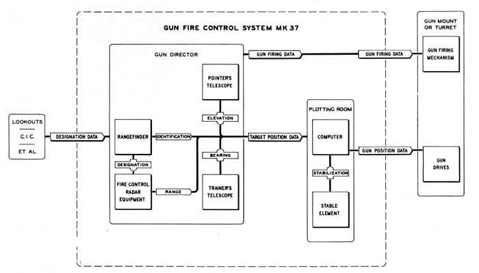
Figure
35. Operation of Gun Fire Control System Mk 37 Against Visible Surface Targets.
Method I.
-37-
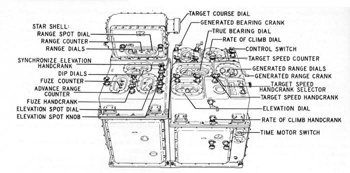
Figure 36. Operating Controls for Surface Fire—Computer Mk I.
|
computers,
the fuze must be set manually on SAFE at the gun mount.) Method 2. |
-38-
|
In
this method, elevation data is obtained from the stable element instead of from
the gun director. An advantage of this method is that it replaces a human (the
director pointer) with a mechanism, thereby reducing the probability of personnel
errors, and it usually gives a smaller dispersion in range, which is sometimes
desirable. This method MUST be used when the large circle scan of Radar Equipment
Mk 25 is being used for spotting purposes because the director pointer must elevate
some 5 degrees above the target so that the trainer may get a type B presentation
for deflection spotting. If the computer dip dials (fig. 36) are calibrated for
the mean trunnion height that exists on the ship, the effectiveness of method
2 is not materially different from the effectiveness of method 1. Obscured
Surface Targets Surface Spotting (with Radar Equipment Mk 25) |
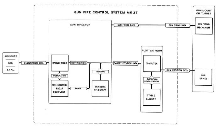
Figure
37. Operation of Gun Fire Control System Mlt 37 Against Visible Surface Targets.
Method 2.
-39-
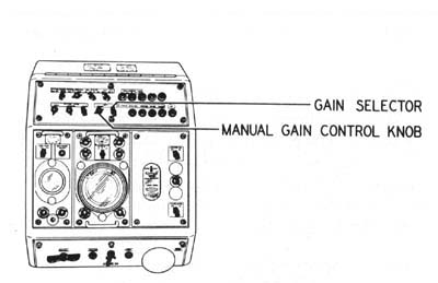
Figure 38. Radar Console Mk 5.
| a.
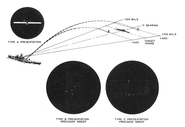
Set the GAIN selector at MAN. This permits manual control of the receiver gain. b. Set the MANUAL gain control knob at its clockwise limit. This gives the maximum gain which is necessary for observing shell splashes. AT THE POINTER'S AND TRAINER'S STATION: a. Press the pointer's and trainer's Transfer Switches Mk 13 (fig. 33). The TRACK lights and READY lights of the Radar Indicators Mk 21 and Mk 22 should go out, indicating that automatic tracking has ceased. b. Set the antenna scan selector (fig. 15) at CIRCLE. This makes the antenna scan approximately a 2-degree annular ring with a mean diameter of 10 degrees. c. Manually track the target in train by turning the trainer's handwheel to keep the target pip aligned with the vertical index in the type B presentation of the Radar Indicator Mk 21. Keep the trainer's rate control key (fig. 33) closed when "on target." d. Turn the pointer's handwheel until the target is at the lower edge of the type E presentation (fig. 39) of the Radar Indicator Mk 22. This elevates the director approximatey |
Figure
39. Typical Splash Indications.
-40-
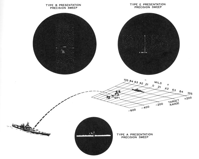
Figure 40. Splash Indication of a Six Gun Salvo.
|
5 degrees so that the lower part of the circle-scan annular ring intersects the target. Do not close the pointer's rate control key. AT
THE CONTROL OFFICER'S STATION : OPERATOR'S STATION : |
-41-
|
sides of the target. Since it is known that on precision (PRES) sweep, the range sweep is 4,000 yards long, the distance between the splashes and the target may be easily estimated. In this case, the splash on the left represents a "short" of 400 yards and would require an ADD spot of 400 yards, while the splash on the right would require a DROP spot of 400 yards. The type B and type E presentations corresponding to the problem in figure 39 are shown at the bottom of the figure. The type B presentation indicates that the short splash would require a RIGHT deflection spot, while the long range splash would require a LEFT deflection spot. The magnitude of the required deflection spot may be estimated if it is remembered that, when using circle scan, the field of coverage is 12 degrees wide; hence a splash pip half way between the target pip and the left edge of the type B scan would require a 3-degree or approximately 50 mils RIGHT deflection spot. Thus it can be seen from the type B presentation in figure 39, that the short splash requires a RIGHT deflection spot of approximately 20 mils while the long range splash requires a LEFT deflection spot of approximately 20 mils. The types A, B, and E presentations showing the splashes of a typical 6-gun salvo are shown in figure 40. Since the mean point of impact (M.P.I.) should be spotted to the target, good spots for this situation would be ADD 300 yards and RIGHT 30 mils. Time Constants for Surface Fire Since effective spotting is possible against surface targets, it is important that the gun fire control system have a stable solution so that there will be little dispersion between successive salvos. If the system time constant were left the same as for air targets (fig. 29), each small perturbation in director train would cause a change in the target setup at the counter. This in turn would cause the gun mounts (or turrets) to move, resulting in an unpredictable pattern that would be impossible to spot. For this reason, the system time constant is increased for surface firing. This is accomplished in either of two ways, depending on whether or not Ordalt 2331A has been accomplished. If Ordalt 2331A has not been accomplished, the system time constant is increased by resorting to manual rate control. The procedure for this type of operation is given later in this chapter. |
RANGE
IN YARDS
|
If Ordalt 2331A has been accomplished, the time constant is increased by setting the AIR-SURFACE selector (figure 28) at SURFACE. This makes the solution time constant KR/R'X 1000 seconds, where K represents the time constant change gears in seconds, R is the present range in yards, and R' is the setting of the time constant control transmitter. Since this value becomes rather large at long range (fig. 41), provisions are made to reduce the time constant if necessary. When the sensitivity push button (fig. 28) is pressed, the time constant is reduced to approximately 72/4000 seconds. If the time constant stayed at this value, the system would be too sensitive for surface fire; therefore, after a given delay (2 or 3 seconds), the time constant automatically returns to its previous value which is suitable for tracking and spotting most surface targets. Manual
Rate Control AT
THE COMPUTER (fig. 42) : |
-42-
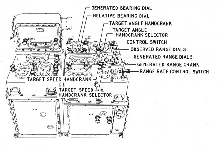
Figure 42. Manual Rate Control—Computer Mk I.
|
tor
at HAND. This de-energizes the target angle servo and permits manual setting of
target angle. Illumination Star shells. |
-43-

Figure 43. Assistant Control Officer's Station—Gun Director Mk 37.
|
order
switches of the star shell mounts at STAR SHELL. Searchlights.
Alternate Methods |
-44-
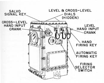
Figure 44. Stable Element Mk 6.
| to
reduce the motion of the guns or the gun director. This may be accomplished by
resorting to selected level or selected cross-level firing. A predetermined value
of either level or cross-level may be selected at the stable element as follows:
 a. At the fuze panel of the fire control switchboard, set the director pointer's firing contact maker switch at OFF and the stable element automatic firing contact maker at ON.  b. At the computer (fig. 36), set the synchronize elevation handcrank at the CENTER position and set the elevation dial at zero. Then set the handcrank at the OUT position and match the dip dials with the advance range counter.  c. At the stable element (fig. 44), set the firing selector switch at LEVEL FIRE or CROSS-LEVEL FIRE, depending on which quantity is to be selected.  d. By means of the proper hand input crank, set the level or cross-level dial at its selected value.  e. Close the automatic firing key. The guns will then fire when the actual value of level or cross level is equal to the selected value. Level may also be selected at the gun director. This may be done as follows:  a. At the computer (fig. 36), set the synchronize elevation hand crank at the CENTER position and set the elevation dial at zero. b. At the gun director, set the elevation selector lever (fig. 25) at LOCAL. Turn the pointer's handwheels (fig. 25) until the elevation indicator is at the desired value of level.  c. Close the pointer's firing key when the horizontal cross hair of the pointer's telescope crosses the target. |
-45-
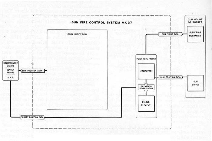
Figure 45. Operation of Gun Fire Control System Mk 37—Indirect Fire.
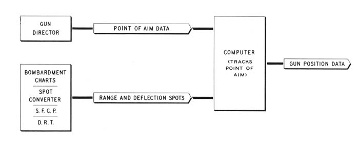
Figure
46. Operation of Gun Fire Control System Mk 37—Offset Fire—Method
I (Point "Oboe" Method).
-46-
SHORE BOMBARDMENT
|
Direct
Fire Indirect
Fire Tracking. Firing. Offset Fire Method
1. |
-47-
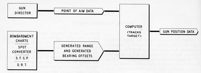
Figure 47. Operation of Gun Fire Control System Mk 37—Offset Fire—Method 2 (Offset Method).
|
shifted from the point of aim to the target by means of the range and deflection spot knobs (fig. 11). This method is limited by the size of the permissible deflection spots to targets within 10 degrees of the point of aim. Consideration of the problem also discloses the fact that, for a moving ship, the required range and deflection spots are continuously changing due to changes in the relative bearing of the point of aim; hence, the spots must be computed and set into the computer continuously. Method 2. The above-mentioned disadvantages of the form of offset fire described under under "Method 1" are eliminated in Method 2 (This method is sometimes called "Offset method"). The operation of the Gun Fire Control System Mk 37 when Method 2 is employed is indicated in figure 47. Here, as in the case of Method 1, the gun director tracks the point of aim. However, offsets are applied to the data furnished to the generating section of the computer so that bearing and range are generated for the point of fall (i.e., the target) rather than the point of aim. This is accomplished by operating the computer in LOCAL control and inserting range and bearing offsets by means of the generated range and generated bearing cranks. To aid in inserting bearing offsets by means of the generated bearing crank, Ordalt 2127 provides for a scale to be attached to the generated bearing crank. The remainder of the problem is handled in the same manner as that previously descripbed under "Indirect fire." Caution. |
Figure 48. A Shore Bombardment Problem. |
-48-
|
Figure 49. Type B Radar Presentations of the Problem in Figure 48. | A
Sample Problem A shore bombardment problem is illustrated in figure 48. The tactical situation is such that it is necessary to destroy: a. the barracks, b. the hangar, c. the airstrip. Naturally, if all of these targets were visible (or good radar targets), direct fire, similar to that outlined for engaging surface targets, would be in order. In this case, however, a smoke screen obscures the entire island and the only good radar target is the hangar. Figure 49 (a) shows a type B presentation (Radar Indicator Mk 21) of this problem with normal (AGC) receiver gain. Since the metal hangar is known to be a good radar reflector, it may be located by setting the GAIN selector (fig. 38) of the Radar Console Mk 5 at MAN and then adjusting the MANUAL gain control knob so that the surrounding land disappears, leaving only the hangar (fig. 49 (b)) as a point of aim. Offset Fire—Method 1 may be used to destroy the barracks by using the hangar as a point of aim and obtaining the required range and deflection spots from a chart. The hangar and airstrip may be destroyed by a rather unique method as follows. The system is set up as usual for direct fire, and destructive fire is started against the hangar. Since it is known that the airstrip lies in a direction 340 degrees from the hangar, the target course dial of the target course indicator (fig. 36) should be set at 340 degrees and the target speed counter at 15 knots. Then the computer time motor switch should be set at ON. With the computer control switch at LOCAL and the Range Rate Control Switch (fig. 27) at MANUAL, this procedure will cause the points of impact of the projectiles to creep down the airstrip. If a projectile is fired every 4 seconds, the hits should be linearly dispersed about every 100 feet on the airstrip. |
-49-